


19
SERVICE (cont.)
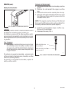
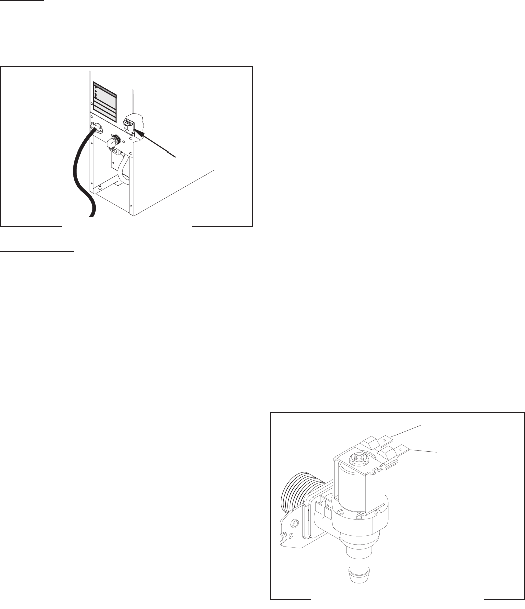
Solenoid Valve
Location:
The solenoid valve is located inside the rear of the
dispenser on the right side near the bottom.
To test the solenoid valve, access will also be needed
to the electronic control board.
7. Check the solenoid valve for coil action. Connect
the dispenser to the power source. Listen carefully
in the vicinity of the solenoid valve for a “clicking”
sound after approximately 5 seconds, as the coil
magnet attracts the plunger.
8. Disconnect the dispenser from the power source.
9. Reconnect the pink wire to terminal 5 of the elec-
tronic control board.
If the sound was heard as described and water will
not pass through the solenoid valve, there may be a
blockage in the water line before or after the solenoid
valve or the solenoid valve may require inspection for
wear and removal of waterborne particles.
If the sound was not heard as described, replace the
solenoid valve.
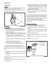
Removal and Replacement:
1. Remove all wires from the solenoid valve coil.
2. Turn-off the water supply to the dispenser.
3. Disconnect the water line from the solenoid
valve.
4. Remove the two 8-32 slotted-head screws holding
the solenoid valve and mounting bracket to the back
panel.
5. Lift-out the solenoid valve.
6. Securely install the new solenoid valve to the back
panel.
7. Securely fasten the water line to the solenoid
valve.
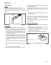
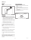
8. Reconnect the wires, FIG. 8.
WARNING
!
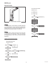
Test Procedure:
1. Disconnect the dispenser from the power source
and turn-off the water supply to the dispenser.
2. Remove the pink wire from terminal 5 of the elec-
tronic control board.
3. Check the voltage across the solenoid valve coil
terminals with a voltmeter. Connect the dispenser
to the power source. The indication must be:
a.) 100 to 120 volts ac for 100 to 120 volt models
or
b.) 200 to 240 volts ac for 200 to 240 volt models
or
c.) 230 volts ac for 230 volt models
after a delay of approximately 5 seconds.
4. Disconnect the dispenser from the power source.
If voltage was present as described, proceed to #5.
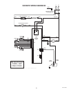
If voltage was not present as described, refer to the
Wiring Diagrams and check the dispenser wiring har-
ness.
5. Remove both wires from the solenoid valve coil
terminals.
6. Check for continuity across the solenoid valve coil
terminals.
If continuity is present as described, reconnect the wires
and proceed to #7.
If continuity is not present as described, replace the
solenoid valve coil.
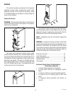
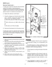
FIG. 7 SOLENOID VALVE
FIG. 8 SOLENOID VALVE WIRING
WHI/BLU to Electronic
Control Board T1
P1778
10420.1 040309
WHI or RED to
Terminal Block