


4
ELECTRICAL REQUIREMENTS
CAUTION: The dispenser must remain disconnected from the power source until specified in Electrical Hook-
Up.
The LCA-2 and LCC-2 dispensers are supplied with a 120-volt / 15 Amp cord set and require a 2-wire, grounded,
individual branch circuit rated for 120 volts AC, 15 amp, single phase, 60Hz. The mating connector must be
a NEMA 5-15R.
The LCA-2C and LCC-2C dispensers are supplied with a 120-volt / 20 Amp cord set and require a 2-wire,
grounded, individual branch circuit rated for 120 volts AC, 20 amp, single phase, 60Hz. The mating connector
must be a NEMA 5-20R.
These dispensers can be Field Wired for 208 or 240 volt applications. This requires a 2 or 3-wire, grounded,
individual branch circuit rated for 208/240 volts AC, 30 amp, single phase, 60 Hz.
NOTE: The internal terminal block must be rewired for 208/240 applications, (see Optional Field Wiring
Diagram).
120V A.C.
120V A.C.
208 or
240V A.C.
HEATER RED
208 or
240V A.C.
120V A.C.
10A. FUSE - WHITE
HEATER RED
10A. FUSE - WHITE
10A. FUSE - BLACK
LIMIT SW. - BLACK
HEATER RED
10A. FUSE - WHITE
10A. FUSE - BLACK
LIMIT SW. - BLACK
10A. FUSE - BLACK
LIMIT SW. - BLACK
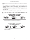
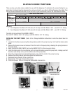
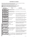
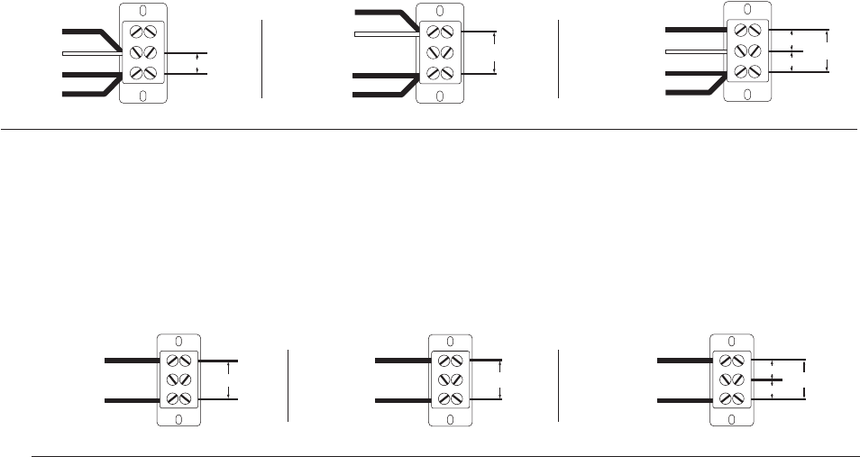
FIELD WIRING TERMINAL BLOCK DIAGRAM
For all 208 - 240 Volt Connections: Use No. 10 AWG Wires suitable for 90°C (194 °F)
1. Unit shipped per Fig. 1, wired for 120V A.C./2-Wire.
2. For 208 - 240V A.C./2-Wire per Fig. 2: Move both the Red-Heater wire and the White-Fuse wire to the Top Red Terminal as shown.
3. For 120/208 - 240V A.C./3-Wire per Fig. 3: Move the Red Heater wire to the Top Red Terminal as shown.
Fig. 1 Fig. 2 Fig. 3
34766 010407
120V A.C.
120V A.C.
208 or
240V A.C.
RED
208 or
240V A.C.
120V A.C.
TO MASTER
ON/OFF
SWITCH
BLACK
RED
TO MASTER
ON/OFF
SWITCH
BLACK
RED
TO MASTER
ON/OFF
SWITCH
BLACK
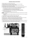
FIELD WIRING TERMINAL BLOCK DIAGRAM
For all 208 - 240 Volt Connections: Use No. 10 AWG Wires suitable for 90°C (194°F)
1. Unit shipped per Fig. 1, wired for 120V A.C./2-Wire.
2. For 208 - 240V A.C./2-Wire per Fig. 2.
3. For 120/208 - 240V A.C./3-Wire per Fig. 3.
Fig. 1 Fig. 2
Fig. 3
FIELD WIRING TERMINAL BLOCK DIAGRAM
Models with Master ON/OFF Switch
FIELD WIRING TERMINAL BLOCK DIAGRAM
Models without Master ON/OFF Switch