Page 28
SERVICE (cont.)
SOLENOID
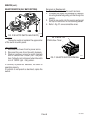
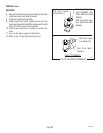
6. Remove the tank inlet tube grommet and discard.
7. Install new tank inlet tube grommet.
8. Install new solenoid assembly.
9. Install liquid level board, shield and secure sole-
noid assembly and shield to the component bracket
with a #10-32 screw and flat washer..
10. Install water inlet tube to connector on the sole-
noid.
11. Turn on the water supply to the brewer.
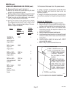
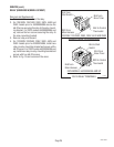
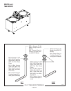
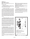
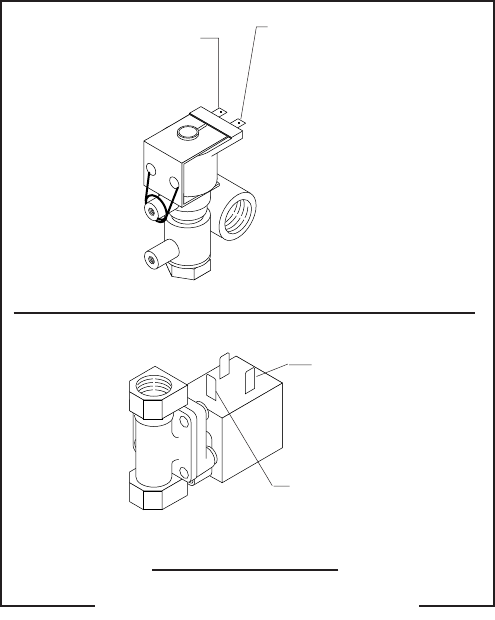
12. Refer to Fig. 23 and reconnect the wires.
BLU from Liquid
Level Board #1
WHI from Main Har-
ness (120/208V, 120/
240V, 380V and 440V
Models)
RED from Main Har-
ness (208V and 240V
Models)
BLK from Main
Harness
BLU from Liquid
Level Board #1
230V - CE MODELS
FIG. 23 SOLENOID TERMINALS
P1741
10060 080900


