


Page 13
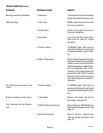
SERVICE (cont.)
10860 090800
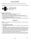
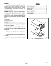
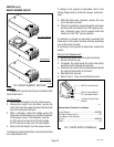
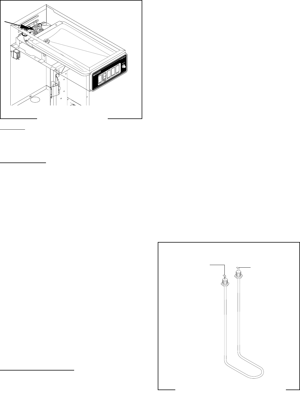
TANK HEATER
P1161.40
Location:
The tank heater is located inside the tank and
secured to the tank lid.
Test Procedures:
1. Disconnect the brewer from the power supply.
2. With a voltmeter, check the voltage across the
black and white wires on the tank heater. Connect
the brewer to the power source. The indication
must be:
a) 100 volts ac for two wire 100 volt models.
b) 120 volts ac for two wire 120 volt models.
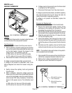
3. Disconnect the brewer from the power source.
If voltage is present as described, proceed to #4
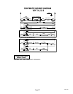
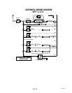
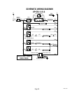
If voltage is not present as described, refer to the
Wiring Diagrams
and check wiring harness.
4. Disconnect the black wire and the white wire from
the tank heater terminals.
5. Check for continuity across the tank heater termi-
nals.
If continuity is present as described, reconnect the
wires, the tank heater is operating properly.
If continuity is not present as described, replace the
tank heater.
NOTE- If the tank heater remains unable to heat,
remove and inspect heater for cracks in the sheath.
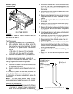
Removal and Replacement:
1. Remove the tank inlet fitting securing the fill basin
to the tank lid, remove fill basin and tank inlet
gasket. Set all three parts aside for reassembly.
2. Disconnect the black wire on the limit thermostat
from the tank heater switch and disconnect the
blue wire from the limit thermostat to the control
thermostat.
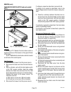
3. Disconnect the black wire and the white wire from
the tank heater terminals.
4. Remove sprayhead and the hex nut securing the
sprayhead tube to the hood. Set aside for reas-
sembly.
5. Remove the eight #8-32 nuts securing the tank lid
to the tank.
6. Remove the tank lid with limit thermostat, spray-
head tube and tank heater
7 Remove the two hex nuts securing the tank heater
to the tank lid. Remove tank heater with gaskets
and discard.
8. Install new tank heater with gaskets on the tank lid
and secure with two hex nuts.
9. Install tank lid with limit thermostat, sprayhead
tube and tank heater using eight #8-32 hex nut.
10. Secure spayhead tube to hood using a hex nut.
11. Install sprayhead.
12. Reconnect the wires to the limit thermostat, tank
heater and control thermostat. See
Limit Thermo-
stat
and
Control Thermostat
sections in this manual
when reconnecting wires.
13. Install fill basin, secure with tank inlet fitting and
gasket.
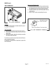
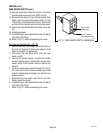
14. Refer to Fig. 9 when reconnecting the tank heater
wires.
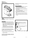
FIG. 8 TANK HEATER
P1163
FIG. 9 TANK HEATER TERMINALS
BLK to Control
Thermostat
WHI to WHI Lead on
Power Cord (120V
Models)
WHI to Terminal Block
(White Insert) (100 V
Models)