


Page 16
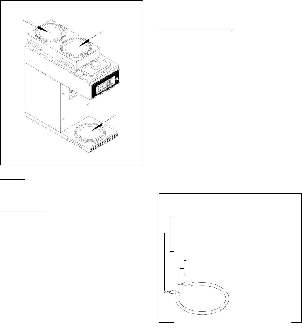
WARMER ELEMENT(S)
P1167
SERVICE (cont.)
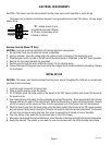
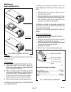
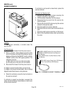
Location:
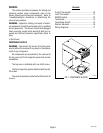
The warmer element(s) is located under the
warmer plate.
Test Procedures:
1. Disconnect the brewer from the power source.
2. With a voltmeter, check voltage across the white
wire to the power cord and the white/red, brown/
black or violet wire to the "ON/OFF" switch, with the
"ON/OFF" switch in the "ON" (upper) position. The
indication must be:
a) 100 volts ac for two wire 100 volt models.
b) 120 volts ac for two wire 120 volt models.
3. Disconnect the brewer from the power source.
If voltage is present as described, proceed to #4.
If voltage is not present as described, refer to
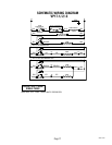
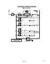
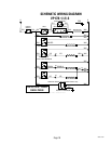
Wiring
Diagrams
and check brewer wiring harness.
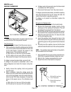
4. Check the continuity across the two terminals on
the warmer element.
If continuity is present as described, reconnect the
white wire and white/red, brown/black or violet wires
on the warmer element.
C
A
U
T
I
O
N
:
W
A
R
M
E
R
S
A
N
D
S
U
R
F
A
C
E
S
A
R
E
H
O
T
C
A
U
T
IO
N
CAUTION
D
I
S
C
A
R
D
D
E
C
A
N
T
E
R
DISCARD DECANTER
I
F
:
IF:
.
C
R
A
C
K
E
D
. CRACKED
.
S
C
R
A
T
C
H
E
D
. SCRATCHED
.
B
O
I
L
E
D
D
R
Y
. BOILED DRY
.
H
E
A
T
E
D
W
H
E
N
E
M
P
T
Y
. HEATED
WHEN EMPTY
.
U
S
E
D
O
N
H
I
G
H
F
L
A
M
E
. USED ON HIGH FLAME
.
O
R
E
X
P
O
S
E
D
E
L
E
C
T
R
I
C
. OR EXPOSED ELE
CTRIC
E
L
E
M
E
N
T
S
ELEMENTS
F
A
I
L
U
R
E
T
O
C
O
M
P
L
Y
R
I
S
K
S
I
N
J
U
R
Y
FAILURE TO COMPLY RISKS INJURY
P
N
:
6
5
8
PN: 658
1
9
85
B
U
NN
-
O
-
M
A
T
IC
C
O
R
P
O
R
AT
IO
N
1985 BUNN-O-MATIC C
ORPORA
TION
F
U
N
N
E
L
C
O
N
T
E
N
T
S
FUNNEL CONTENTS
A
R
E
H
O
T
ARE HOT
!
B
U
N
N
®
VP-17 SERIES
R
E
A
D
Y
L
O
W
E
R
T
O
P
C
A
U
T
I
O
N
:
W
A
R
M
E
R
A
N
D
S
U
R
F
A
C
E
S
A
R
E
H
O
T
P
O
U
R
IN
W
A
T
E
R
O
N
L
Y
P1164
If continuity is not present as described, replace the
warmer element.
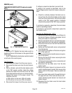
Removal and Replacement:
1. Remove the three #4-40 screws securing the
warmer assembly to the brewer.
2. Lift the warmer assembly from the brewer.
3. Disconnect the two wires from the warmer ele-
ment terminals.
4. Remove the two #8-32 nuts securing the warmer
element to the warmer plate.
5. Securely install new warmer element.
6. Reconnect the two wires to warmer element termi-
nals.
7. Securely install warmer assembly on the brewer.
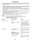
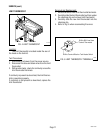
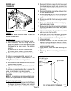
8. Refer to the illustration below when reconnecting
the wires.
FIG. 13 WARMER ELEMENT TERMINALS
WHI to WHI Lead on Power Cord (120V Brewers)
WHI to Terminal Block (100V Brewers)
WHI/RED to ON/OFF Switch (One Lower Warmer)
BRN/BLK to ON/OFF Switch (to Front Warmer or
Side Warmer)
VIO to ON/OFF Switch (Top Rear Warmer or Rear
Side Warmer)
10860 121101