


Page 14
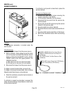
Location:
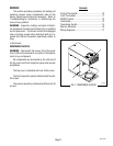
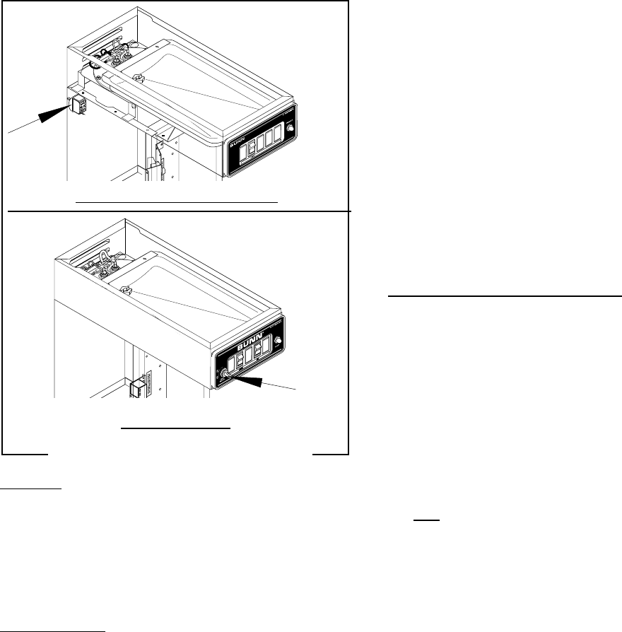
On Early VP17 Models the tank heater switch is
located on the rear of the brewer on the upper left side
of the trunk.
On VP17B Models the tank heater switch is located
on left side of the control panel.
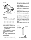
Test Procedure:
1. Disconnect the brewer from the power source.
2. Disconnect the black wire from the limit thermo-
stat.
3. With a voltmeter, and with the tank heater switch
in the "ON" (upper) position check the voltage
between the black wire removed from the limit
thermostat and the white wire on the tank heater.
Connect the brewer to the power source. The
indication must be:
a) 100 volts ac on two wire 100 volt models.
b) 120 volts ac on two wire 120 volt models.
4. Disconnect the brewer from the power source.
If voltage is present as described, proceed to #5.
If voltage is not present as described, refer to the
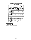
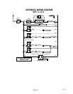
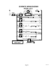
Wiring Diagrams
and check the brewer wiring har-
ness.
5. Check for continuity between the black wire re-
moved from the limit thermostat and the black
insert on the terminal block, with the tank heater
switch in the "ON" (upper) position. Continuity
should not be present in the "OFF" (lower) position.
If continuity is present as described, the tank heater
switch is operating properly.
If continuity is not present as described, replace the
tank heater switch.
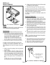
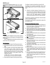
Removal and Replacement: (VP17)
1. Remove the tank inlet fitting securing fill basin to
the tank lid. Remove fill basin and gasket. Set all
three parts aside for reassembly.
2. Remove sprayhead and hex nut securing spray-
head tube to the hood. Set aside for reassembly.
3. Disconnect the wires on the limit thermostat and
the tank heater.
4. Gently pull the thermostat sensor and grommet
from the tank lid.
5. Insert a tube to the bottom of the tank and syphon
ALL of the water out.
6. Gently reinstall the thermostat sensor and grom-
met in the tank lid.
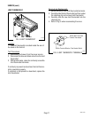
7. Remove the two #8-32 screws securing the tank
assembly to the hood.
8. Lift tank and components out as an assembly and
set aside for reassembly.
9. Disconnect the two black wires from the tank
heater switch.
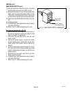
10. Remove the plastic facenut, hex facenut and the
switch indicator/guard bracket that secures tank
heater switch to the brewer. Remove switch and
discard.
11. Insert new tank heater switch through the hole in
the upper left rear of the trunk and secure with
switch indicator/guard bracket, hex facenut and
plastic facenut.
12. Reconnect the two black wires the tank heater
switch terminals.
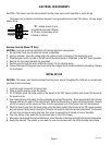
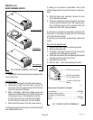
TANK HEATER SWITCH (VP17B and early model
VP17)
P1161.40
VP17 MODELS (Early Models)
VP17B MODELS
P1319.40
SERVICE (cont.)
FIG. 10 TANK HEATER SWITCH
10860 061501