


8
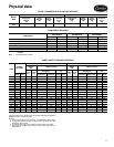
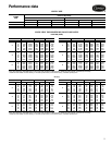
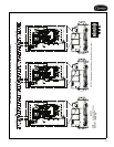
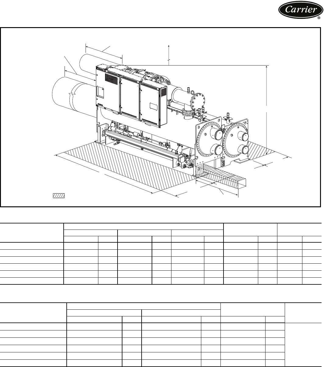
23XRV DIMENSIONS (NOZZLE-IN-HEAD WATERBOX)
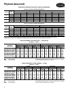
23XRV DIMENSIONS (MARINE WATERBOX)
*Assumes both cooler and condenser nozzles on same end of chiller.
†1 or 3 pass length applies if cooler is a 1 or 3 pass design.
NOTES:
1. Service access should be provided per American Society of Heat-
ing, Refrigerating, and Air Conditioning Engineers (ASHRAE) 15,
latest edition, National Fire Protection Association (NFPA) 70, and
local safety code.
2. Allow at least 3 ft (915 mm) overhead clearance for service rigging
for the compressor.
3. Certified drawings available upon request.
4. Marine waterboxes may add 6 in. (152 mm), to the width of the
machine. See certified drawings for details.
5. ‘A’ length and ‘B’ width dimensions shown are for standard
150 psig (1034 kPa) design and victaulic connections. The
300 psig (2068 kPa) design and/or flanges will add length. See cer-
tified drawings.
6. Dished head waterbox covers not available for the 3-pass design.
HEAT EXCHANGER
SIZE
A (Length, with Nozzle-in-Head Waterbox)
B (Width) C (Height)
1 Pass 2-Pass* 3 Pass
ft-in. mm ft-in. mm ft-in. mm ft-in. mm ft-in. mm
30 to 32 14- 3
1
/
4
4350 13- 8
1
/
4
4172 14- 3
1
/
4
4350 6- 4 1930 7- 2
5
/
8
2200
35 to 37 15-11
3
/
4
4870 15- 4
3
/
4
4693 15-11
3
/
4
4870 6- 4 1930 7- 2
5
/
8
2200
40 to 42 14- 9 4496 14- 3
1
/
8
4347 14- 6 4420 6- 8
1
/
2
2045 7- 6
1
/
2
2299
45 to 47 16- 5
1
/
2
5017 15-11
5
/
8
4867 16- 2
1
/
2
4940 6- 8
1
/
2
2045 7- 6
1
/
2
2299
50 to 52 14-10 4521 14- 4
1
/
2
4382 14- 6
1
/
2
4432 6-11
3
/
4
2127 7- 6
3
/
4
2305
55 to 57 16- 6
1
/
2
5042 16- 1 4902 16- 3 4953 6-11
3
/
4
2127 7- 6
3
/
4
2305
HEAT EXCHANGER
SIZE
A (Length, Marine Waterbox)
B (Width)
C (Height)2-Pass* 1 or 3 Pass†
ft-in. mm ft-in. mm ft-in. mm
30 to 32 14- 9 4496 16- 4
3
/
4
4997 6- 9
3
/
8
2067
See unit
certified
drawings
35 to 37 16- 5
1
/
2
5017 18-1
1
/
4
5518 6- 9
3
/
8
2067
40 to 42 15- 2
3
/
4
4642 16- 3
1
/
4
50866-9
3
/
4
2076
45 to 47 16-11
3
/
4
5163 18-4
3
/
4
5607 6- 9
3
/
4
2076
50 to 52 15- 3
1
/
2
4661 16- 8
1
/
2
5093 7- 1 2159
55 to 57 17- 0 518218- 5 5613 7- 1 2159
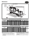
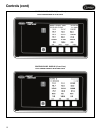
B
(WIDEST POINT)
2’ MIN
(610 mm)
4’-10” MIN
(1475 mm)
A
C
FRAME R COMPRESSOR 3’-0” (915mm)
RECOMMENDED OVERHEAD SERVICE CLEARANCE
MOTOR SERVICE
CLEARANCE
1’-10” (559 mm)
TUBE REMOVAL
SPACE FOR
EITHER END
SIZES 30-32, 40-42
50-52
14’-3” (4343 mm)
SIZES 35-37, 45-47
55-57
14’-0” (4267 mm)
SERVICE AREA
4’ MIN
(1219 mm)
23XRV DIMENSIONS
a23-1646
Dimensions