Manufacturer reserves the right to discontinue, or change at any time, specifications or designs without notice and without incurring obligations.
PC 903 Catalog No. 563-068 Printed in U.S.A. Form 30GTN-10SI Pg 1 1-00 Replaces: New
Book 2
Ta b 5 c
Installation Instructions
CONTENTS
Page
SAFETY CONSIDERATIONS
. . . . . . . . . . . . . . . . . . . . . . 1
INSTALLATION
. . . . . . . . . . . . . . . . . . . . . . . . . . . . . . . . .1-11
Step 1 — Rig and Place the Unit
. . . . . . . . . . . . . . . . . . 1
• RIGGING
• PLACING UNIT
• MOUNTING UNIT
Step 2 — Check Compressor Mounting
. . . . . . . . . . 3
Step 3 — Cooler Fluid and Drain Piping
Connections
. . . . . . . . . . . . . . . . . . . . . . . . . . . . . . . . . . . . 3
• PREPARATION FOR YEAR-ROUND
OPERATION
• PREPARATION FOR WINTER SHUTDOWN
Step 4 — Make Electrical Connections
. . . . . . . . . . . 7
• POWER SUPPLY
• POWER WIRING
Step 5 — Install Accessories
. . . . . . . . . . . . . . . . . . . . 11
• ELECTRICAL
• HOT GAS BYPASS
Step 6 — Refrigerant Circuit
. . . . . . . . . . . . . . . . . . . . . 11
• LEAK TESTING
• DEHYDRATION
• REFRIGERANT CHARGE
SAFETY CONSIDERATIONS
Installing, starting up, and servicing air-conditioning equip-
ment can be hazardous due to system pressures, electrical com-
ponents, and equipment location (roofs, elevated structures,
etc).
Only trained, qualified installers and service mechanics
should install, start up, and service this equipment (Fig. 1).
Untrained personnel can perform basic maintenance func-
tions such as cleaning coils. All other operations should be per-
formed by trained service personnel.
When working on the equipment, observe precautions in the
literature and on tags, stickers, and labels attached to the
equipment.
• Follow all safety codes.
• Wear safety glasses and work gloves.
• Keep quenching cloth and fire extinguisher nearby when
brazing.
• Use care in handling, rigging, and setting bulky
equipment.
• See Tables 1A and 1B for Physical Data.
INSTALLATION
Step 1 — Rig and Place the Unit
RIGGING — Preferred method is with spreader bars from
above the unit. Use 2-in. (50 mm) OD pipe or hooks in lifting
holes. Rig with 4 cables and spreader bars. All panels must be
in place when rigging. See rigging label on unit for details con-
cerning shipping weights, distance between lifting holes, center
of gravity, and spreader bar dimensions. See Fig. 2.
If overhead rigging is not possible, place chiller on skid or
pad for rolling or dragging. When rolling, use a minimum of
3 rollers. When dragging, pull the pad. Do not apply force to
the unit. When in final position, raise from above to lift unit off
pad.
PLACING UNIT — There must be at least 4 ft (1.2 m) for
service and for unrestricted airflow on all sides of unit, and a
minimum of 8 ft (2.4 m) clear air space above unit. Provide
ample room for servicing cooler. For cooler removal see clear-
ance requirements in Fig. 3-5. For multiple units, allow 8 ft
(2.4 m) separation between units for airflow and service.
If unit is to be used in an area with high solar radiation,
mounted position should be such that control box is not ex-
posed to direct solar radiation. Exposure to direct solar radia-
tion could affect the temperature switch controlling cooler
heaters. See Table 2.
ELECTRIC SHOCK HAZARD
Open all remote disconnects before servicing
this equipment.
All panels must be in place when rigging.
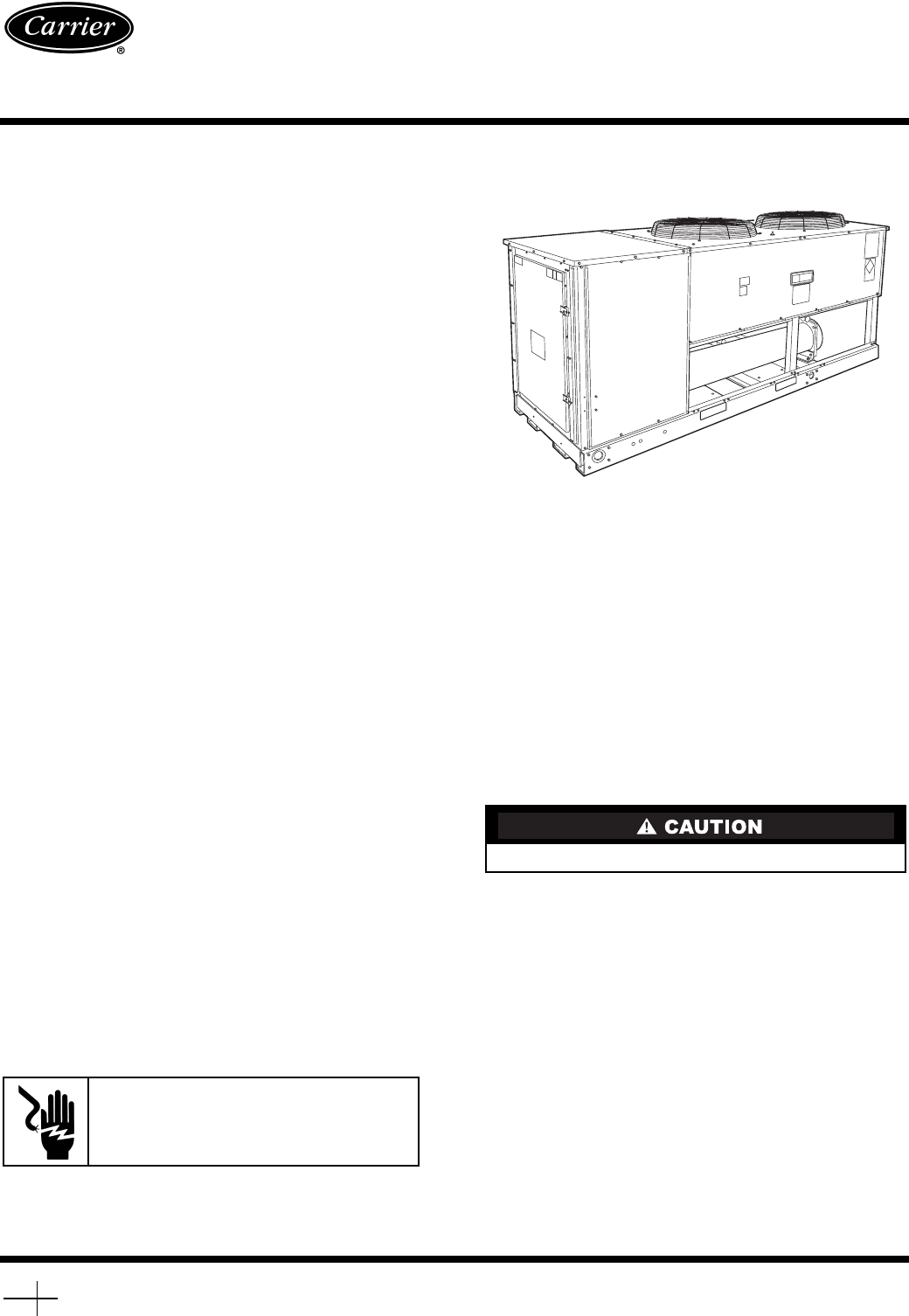
30GTN015-035
Reciprocating Liquid Chillers
with ComfortLink™ Controls
50/60 Hz
Fig. 1 — Model 30GTN (020 Shown)


