


3
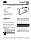
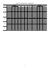
Table 2 — Temperature Limits for Standard Units
LEGEND
*For sustained operation, EWT should not exceed 85 F (29.4 C).
†Unit requires modification below this temperature.
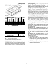
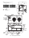
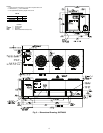
MOUNTING UNIT — When unit is in proper location, use
of mounting holes in base rails is recommended for securing
unit to supporting structure, or for mounting unit on vibration
isolators if required. See Fig. 3-5. Fasteners for mounting unit
are field supplied. Be sure unit is level to ensure proper oil
return to compressor.
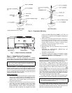
Step 2 — Check Compressor Mounting —
As
shipped, compressor is held down by 4 bolts. After unit is in-
stalled, loosen each bolt using nut indicated in Fig. 6 until the
flat washer (
3
/
8
in.) can be moved with finger pressure.
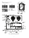
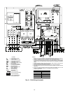
Step 3 — Cooler Fluid and Drain Piping Con-
nections —
When facing the cooler side of the unit, the re-
turn water connection is on the left and the leaving water con-
nection is on the right. See Fig. 3-5 and 7. Install a minimum
40-mesh strainer in the cooler fluid inlet line just ahead of and
as close as possible to the cooler. Provide a means of venting
air from the high point of the field-installed piping.
After field piping is complete, freeze-up protection is rec-
ommended using inhibited ethylene glycol or other suitable in-
hibited antifreeze solution and electric heat tapes in area where
piping is exposed to low ambient temperatures (34 F [1 C] or
below). Heat tapes should possess a rating for area ambients
and be covered with a suitable thickness of closed-cell
insulation. Route power for heating tapes from a separately-
fused disconnect. Identify disconnect as heat tape power source
with a warning that power must not be turned off except when
unit is being serviced.
The cooler drain connection is at the opposite end from the
compressor (See Fig. 3-5). Insulate the drain piping (in the
same manner as the chilled water piping) for at least one ft
(305 mm) from cooler.
PREPARATION FOR YEAR-ROUND OPERATION — If
unit is on year-round operation, add sufficient inhibited ethyl-
ene glycol or other suitable inhibited antifreeze solution to
chilled water to prevent freezing under low-ambient operating
conditions. Consult local water authority on characteristics of
area water and add a recommended inhibitor to the chilled
water.
PREPARATION FOR WINTER SHUTDOWN — Do not
shut off control power disconnect during off-season shutdown.
At end of cooling season:
1. Drain water from system.
2. Replace drain plug and put 2 gallons (8 liters) of inhib-
ited ethylene glycol (or other suitable inhibited anti-
freeze) in cooler to prevent freezing of residual water.
(Remove plug on top of leaving chilled water nozzle to
add liquid.)
3. At the beginning of the next cooling season, refill cooler
and add recommended inhibitor.
TEMPERATURE F C
Maximum Ambient Temperature 125 52
Minimum Ambient Temperature 0–18
Maximum Cooler EWT* 95 35
Maximum Cooler LWT 70 21
Minimum cooler LWT† 38 3.3
EWT — Entering Fluid (Water) Temperature
LWT — Leaving Fluid (Water) Temperature
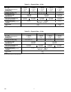
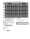
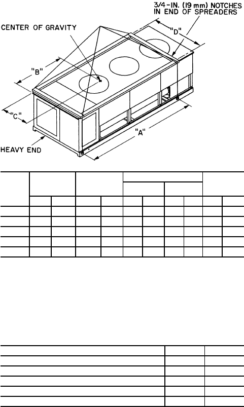
UNIT
30GTN
MAXIMUM
SHIP WT
LIFTING
HOLES
“A”
CENTER OF GRAVITY
“D”
“B” “C”
Lb Kg in. mm in. mm in. mm in. mm
015 1876 851 94.0 2388 48.0 1219 23.0 583 49.5 1256
020 2031 921 94.0 2388 47.5 1207 23.0 583 49.5 1256
025 2415 1095 94.0 2388 51.0 1295 34.5 876 73.5 1867
030 2606 1182 94.0 2388 51.0 1295 34.5 876 73.5 1867
035 3365 1526 127.0 3225 66.5 1689 35.5 901 73.5 1867
Fig. 2 — Rigging with Spreader Bars
(Field Supplied)