


11
Step 5 — Install Accessories
ELECTRICAL — A number of electrical accessories are
available to provide the following optional features (for details,
refer to the Controls, Start-Up, Operation, Service, and
Troubleshooting book):
• Energy Management Module (used for any of the fol-
lowing types of temperature reset, demand limit and ice
features):
— 4 to 20 mA leaving fluid temperature reset (requires
field-supplied 4 to 20 mA generator)
— 4 to 20 mA cooling set point reset (requires field-
supplied 4 to 20 mA generator)
— Discrete inputs for 2-step demand limit (requires field-
supplied dry contacts)
— 4 to 20 mA demand limit (requires field-supplied 4 to
20 mA generator)
— Discrete input for Ice Done switch (requires field-
supplied dry contacts)
• Chilled fluid flow switch/interlock
• Navigator display:
Provides hand-held, mobile capability using easy to read
4-line display. Keypad function is the same as the Scrolling
Marquee module. Features magnet for ‘hands free’ service
of components.
HOT GAS BYPASS — Hot gas bypass usually is not rec-
ommended because it results in application of equipment out
of its normal design application range. However, if its use is
required, the appropriate hot gas bypass package may be used.
For installation details, refer to separate instructions supplied
with the accessory package.
Step 6 — Refrigerant Circuit
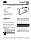
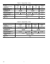
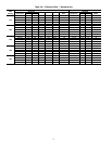
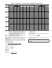
LEAK TESTING — Units are shipped with complete op-
erating charge of R-22 (see Tables 1A-1B) and should be
under sufficient pressure to conduct a leak test. If there is no
pressure in the system, use standard refrigeration practices to
search for the leak. Repair the leak using good refrigeration
practices. After leaks are repaired, system must be evacuated
and dehydrated prior to recharging with refrigerant.
DEHYDRATION — Refer to Carrier Standard Service Tech-
niques Manual, Chapter 1, Refrigerants, Sections 6 and 7 for
details. Do not use compressor to evacuate system.
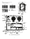
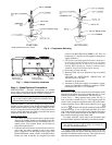
REFRIGERANT CHARGE (Refer to Table 1A or 1B) —
Immediately ahead of filter drier in each circuit is a factory-
installed liquid line service valve. Each valve has a
1
/
4
-in.
Schrader connection for charging liquid refrigerant.