


7
Step 4 — Make Electrical Connections
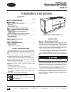
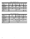
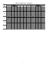
POWER SUPPLY — Electrical characteristics of available
power supply must agree with unit nameplate rating. Supply
voltage must be within limits shown in Tables 3A and 3B.
POWER WIRING — All power wiring must comply with ap-
plicable local and national codes. Install field-supplied branch
circuit fused disconnect(s) per NEC (National Electrical Code,
U.S.A.) of a type that can be locked OFF or ON. Disconnect(s)
must be within sight from and readily accessible from unit in
compliance with NEC Article 440-14.
General Wiring Notes
1. The control circuit power must be from a separate source
and must be brought through a field-supplied fused dis-
connect rated at 15 amps for 230-v and 30 amps for 115-v
control power. Two terminal blocks are provided for
field-wired control devices.
2. Crankcase and cooler heaters are wired in the control cir-
cuit so they are always operable as long as the control
power disconnect is on and safety device is open or the
Enable-Off-Remote contact switch is in the Off position.
Heaters are wired so that they are energized even when
power to the Main Base Board (MBB) is off. They are
protected by a 7-amp fuse in field-supplied control power
supply disconnect.
3. The control circuit field-supplied disconnect should never
be off except when unit is being serviced or is to be down
for a prolonged period, in which case cooler should be
drained. When operation is resumed, crankcase heater
should be energized for 24 hours before start-up.
4. Power entry is at one end only.
5. Maximum field wire sizes allowed by lugs on terminal
block are:
350 kcmil for 30GTN030,035 (208/230-3-60) and
30GTN030 (230-3-50) units.
2/0 AWG for all other units.
6. Terminals for field power supply are suitable for copper,
copper-clad aluminum, or aluminum conductors. Insula-
tion must be rated 167 F (75 C) minimum.
Field Connections
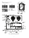
Main Power — Bring wires from the fused disconnect switch
through hole in bottom rail of unit to control box (Fig. 3-5) and
connect to terminals on terminal block TB1 (See Fig. 8).
Control Power — Bring separate source power (see Fig. 8,
note 2) into unit as shown in Fig. 3-5. This supplies power for
control circuit, compressor crankcase heater, and cooler heater.
Connect incoming wires to TB4 in unit control box (L1 to
and L2 to ). Neutral side must be connected to the neutral
terminal block (by C-A1) for 380-3-60 and 400-3-50 V units
only. In the auxiliary power supply a field-supplied disconnect
with 15-amp circuit protection must be provided to accommo-
date crankcase heater and cooler heater cable.
To comply with NEC Article 440-14, the disconnect must
be located within sight from and readily accessible from unit.
A toggle switch (marked Emergency On-Off on the unit
label diagram and by the switch) allows the control circuit to be
manually disconnected when necessary. This switch does not
affect the crankcase heater and cooler heater cable.
IMPORTANT: Operating unit on improper supply volt-
age or with excessive phase imbalance constitutes abuse
and may affect Carrier warranty.
IMPORTANT: To ensure power to the heaters, make
sure auxiliary power to unit is always on (except for
servicing or prolonged shutdown).
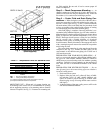
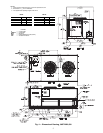
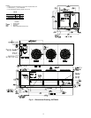
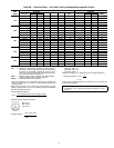
NOTE: All dimensions are in inches.
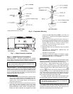
Fig. 6 — Compressor Mounting
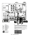
Liquid Chiller
OUT
IN
REFRIGERATING
MACHINE
U.N.2857
WATER INLET
(RETURN WATER)
WATER OUTLET
(LEAVING WATER)
WATER
DRAIN
Fig. 7 — Water Connection Locations