


2
Step 2 — Install Piping
NOTE: The units have 2 circuits. Perform all of the following
piping installation procedures on both A and B circuits.
REMOVE MINIMUM LOAD PORT PLUGS AND IN-
STALL FITTINGS — Plugs must be removed from these
ports and replaced with O-ring seal fittings. Note that plugs
were factory-installed with Loctitet 554 or equivalent
refrigerant-compatible sealant. Fittings should be installed with
similar sealant on threads.
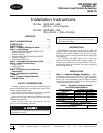
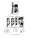
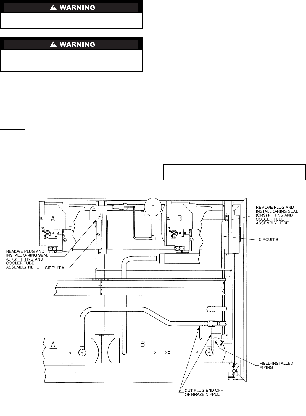
30GXN,R
— Cut plug end off of minimum load port braze
nipple on discharge line, located between oil separator and con-
denser. Remove plug from minimum load port on cooler shell.
See Fig. 1. Using thread sealant, install O-ring seal fitting in
minimum load port on cooler. Port on nipple in discharge line
is reserved for a brazed connection.
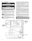
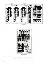
30HX
— Remove plugs from minimum load ports on the cool-
er shell and the condenser shell (30HXC) or oil separator
(30HXA). See Fig. 2. Using thread sealant, install O-ring seal
fittings in minimum load ports.
INSTALL PIPING — On 30GXN,R units, carefully thread the
cooler tube assemblies (P/N 30GX503487) on the O-ring seal
fittings installed in the cooler port. Do not tighten. Install field-
supplied
5
/
8
-in. OD copper tubing between the tube assembly
and the brazed nipple on the discharge line.
On 30HX units, carefully thread the cooler tube assemblies
(P/N 30GX503487) and the condenser oil separator tube as-
sembly (P/N 30HX402343) on the O-ring seal fittings installed
in the cooler and condenser/oil separator ports. Do not tighten.
Install field-supplied
5
/
8
-in. OD copper tubing between the
tube assemblies on the cooler shell and condenser (30HXC) or
oil separator (30HXA).
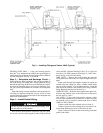
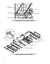
INSTALL BALL AND SOLENOID VALVES — Using good
piping practice, braze ball valve and solenoid valve into
5
/
8
-in.
minimum load piping. Fig. 2 shows a typical 30HX installation
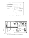
and Fig. 3A and 3B show a typical 30GXN,R installation, in-
cluding valve locations and orientation. Ensure that ball valve
is fully open, and that both the ball and solenoid valve are pro-
tected from excess heat during brazing process. Wrap wet
cloths around valve bodies and tube assembly locking nuts
during brazing to prevent damage to the valves and O-rings
from heat.
CONNECT PIPING — Lubricate O-rings with a light coating
of polyalphaolefin lubricant suitable for R-134a systems.
Thread tube assembly nuts onto the O-ring seal fittings until
they are finger-tight. Lightly snug the nut with a wrench;
DO NOT OVER TIGHTEN. You should be able to feel the O-
ring compress on the last
1
/
4
-turn.
Shut off all power to the unit, then lock out and safety-tag
all disconnects before proceeding with installation.
Remove refrigerant charge from circuits using an ap-
proved refrigerant recovery device before proceeding with
installation.
IMPORTANT: DO NOT over tighten the O-ring seal
nut. Damage will occur to the seal, resulting in leaks.
Fig. 1 — Installing Fittings, 30GXN,R (Typical Size 080-150, 160 Shown)
→
102