


3
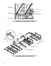
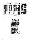
30GXN,R UNITS ONLY — Using good brazing practice,
braze the
5
/
8
-in. minimum load tubing to the copper nipple on
the discharge line (minimum load port) between the condenser
coil and oil separator. See Fig. 1, 3A and 3B.
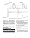
Step 3 — Dehydrate and Recharge Circuit —
When piping has been completed, leak test the assembly. If
one of the O-ring seal fittings leaks, slowly tighten the O-ring
nut until the leak stops. If this does not fix the leak, the connec-
tion must be reinstalled using a new O-ring in the fitting. Con-
tact your Carrier representative for assistance in locating these
parts.
After leak testing, evacuate, dehydrate, and recharge the cir-
cuit using an approved refrigerant recovery device. Correct
type and amount of refrigerant are listed on unit nameplate and
in base unit documentation.
Step 4 — Install Control Wiring
Wires between field-installed components and unit control
box must be enclosed in field-supplied conduit. Follow all local
codes and NEC (National Electrical Code, U.S.A.). Wire size
must be no. 16 AWG (American Wire Gage) (1.5 mm
2
) mini-
mum. See Fig. 4 and 5 for field wiring.
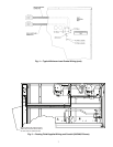
30HX UNITS — Remove the screws holding the right-side
access panel to the unit control box. Open the right-side access
panel.
Route wires through field-supplied conduit and attach the
conduit to the unit control box, using a suitable conduit fitting
and one of the available
7
/
8
-in. knockout openings. Attach the
other end of the conduit to the solenoid valve, using a suitable
fitting. Repeat for the other circuit. See Fig. 4.
30GXN,R UNITS —Route the field-supplied water proof con-
duit from the solenoid valves to the control box at the end of
the unit. See Fig. 4 and 5.
ALL UNITS — Using good wiring practice, connect a white
wire from the solenoid valve on circuit A to a white wire from
the solenoid valve on circuit B. Connect both wires to TB2-9
(30HX) or TB4-2 (30GX).
Connect a pink wire to the solenoid valve on circuit A.
Connect a gray wire to the solenoid valve on circuit B. Con-
nect both the pink and gray wires to TB5-9 for all units.
Figure 4 shows the correct location of the wiring connection
points on the chiller.
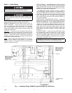
Be sure all power to the unit is off before proceeding. Lock
out and safety-tag all disconnects.
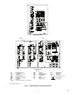
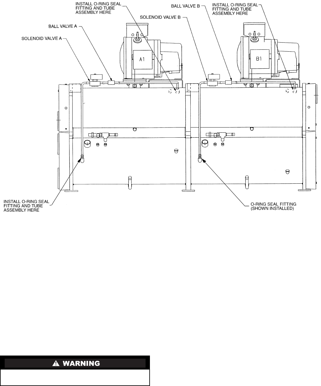
Fig. 2 — Installing Fittings and Valves, 30HX (Typical)