


9
Installation
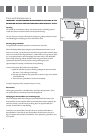
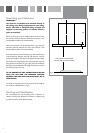
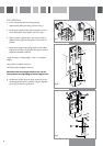
4. Insert 3 screws into the main fixings, leaving
approximately 3mm protruding, as shown in Fig 7
5. Fit the upper support section (B) into position on the 3
screws and rotate it into position, as shown in Fig 7.
6. When in position, tighten the 3 main screws and fit an
additional screw (X) to fix the support frame section in
position.
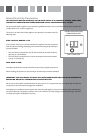
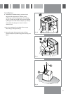
7. Measure the height of the ceiling and then the hotplate
height from the floor. The length of the support sections
should be calculated as follows:
Length of support = Ceiling height – (127 + H + Hotplate
height)
For gas hobs, H=700mm minimum
For electric hobs, H=600mm minimum
Note that if the exact height cannot be set, use the
frame position corresponding to the next highest one.
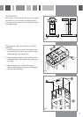
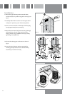
8. Fit the lower section (B) to the upper section (C) at the
correct height and secure in position using the supplied
screws (G), as shown in Figs 8 and 9
Fig. 7
Fig. 8
Fig. 9