


18
SPECIAL COMPONENTS TEST AND ADJUSTMENTS
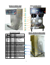
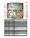
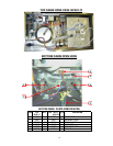
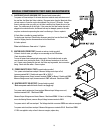
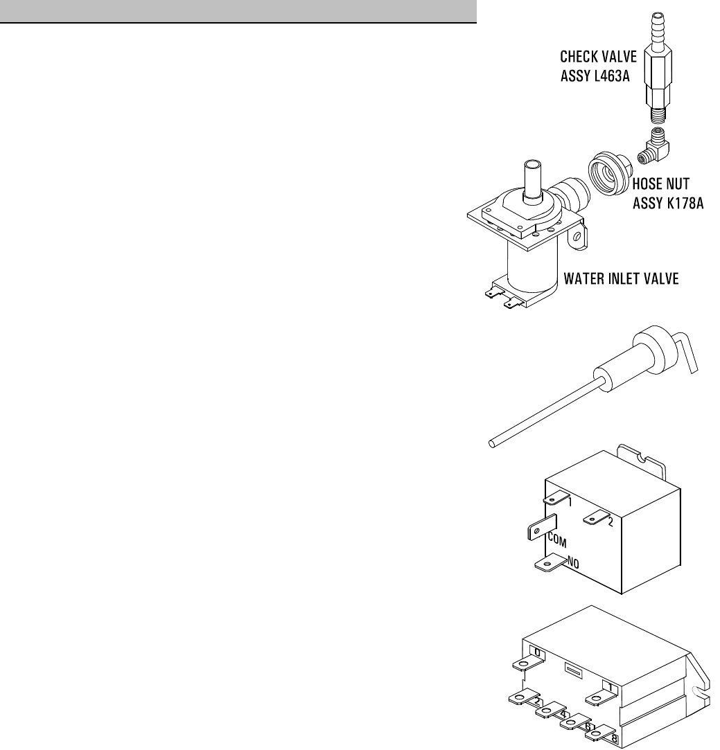
1) WATER INLET VALVE (SOLENOID) TEST (Located inside bottom cabin)
Turn power off from touchpad. If the water level rises inside the tank, and shoots out of
the overflow, the Water Inlet Valve is leaking. Disconnect wires from the Water Inlet Valve
coil and connect a 2 wire line cord to the terminals. Plug it into a 115V outlet. If water
flows in and stops when you pull it out, the Valve is working fine. Repeat this test a few
times. The problem may be in the Probe. If the water does not flow in when the cord is
plugged into an electrical outlet, the Solenoid coil may be damaged, opened or the valve
may have an obstruction preventing the water from flowing in. Clean or replace it.
A Check Valve is installed to prevent backflow.
To check proper function of Check Valve, disconnect water line from the Check Valve,
check for dripping from the disconnected end of the Check Valve.
If it leaks replace it.
Water inlet Valve max. flow rate is 1.3 gal/min.
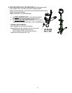
2) WATER LEVEL PROBE TEST (Located on tank top, inside top cabin)
If there is a lack of water, you will get an error message on the LCD window.
Check the probe as follows:
Turn on the power from touchpad and water supply. Check inside the tank to make
sure the water is not touching the Probe. Pull the wire and terminal out of the Probe
rod. If water starts flowing into the tank, the Probe may be grounded, due to excessive
liming. Check with Ohm meter. Clean or replace.
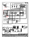
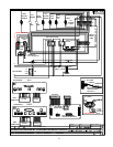
3) POWER SAFETY RELAY TEST (Located inside top cabin)
Turn power switch on from touchpad. Measure Voltage across Input to Coil,
between terminals1& 2. Should read approx. 9V to 10V D.C.
Measure Voltage across Output, between terminals “COM” to Ground. Should read 120V.
Measure Voltage across Input, between terminals “NO” to Ground. Should read 120V.
4) HEATER SAFETY RELAY TEST (Located inside top cabin)
Make sure power switch in back of unit is on (toggle up).
Turn power switch on (energize) from touchpad. Measure Input Voltage across coil,
between terminals 0 & 1. Should read 120V.
Measure Output Voltage across Heater Element. Should read 220 V. If there is no Voltage
across the Heating Element, measure Output Voltage between terminals 4 & 8.
Turn power switch off from touchpad. The Voltage should be a constant 220V even when not energized.
Turn power switch on) from touchpad. Measure Voltage across terminals 2 & 6. Should read 220V.
If 120V was applied to relay coil and it does not energize, replace relay.