


4
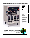
INSTALLATION AND OPERATING INSTRUCTIONS
Warranty is void if the Brewer is connected to any Voltage other than the Voltage specified on the data
label of the Brewer.
UNPACKING AND INSPECTION
Carefully unpack the Brewer by cutting the straps and lifting the carton off the Brewer.
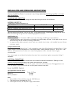
ASSEMBLY AND SET-UP
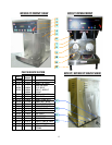
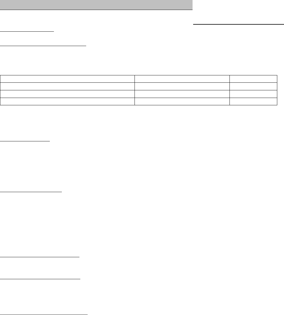
The Brewer is shipped complete with:
DESCRIPTION BC1-301-IT BC2-IT, 302-IT
Adjustable legs 4 4
Carriers complete with Faucets and Covers 1 2
Funnels with sample Filter pack 1 2
Remove carriers from Brewer, one has the four (4) legs packed inside. Install legs by tilting Brewer on its
back and screwing the legs into the threaded leg supports on bottom.
WATER HOOK UP
The National Sanitation Foundation (NSF) requires the following for NSF approved installation:
1. A quick disconnect water connection or enough extra coiled tubing (at least 2x the depth of the unit) so
that the Brewer can be moved for cleaning underneath.
2. An approved flow-back prevention device such as a double check valve to be installed between Brewer
and water supply.
WATER CONNECTION
The Brewer comes equipped with a ¼ inch compression water inlet fitting located in the back. Use a ¼ inch
copper tubing to connect the Brewer to a cold water supply. Water pressure should be: 20 PSI min. to 90
PSI max. An external shut-off valve and a water filtering system with a charcoal filter are highly
recommended.
Turn water supply on and check for leaks at the water inlet connections, tighten compression fitting if
necessary.
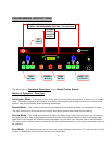
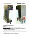
ELECTRICAL CONNECTIONS
A terminal block inside the base compartment is provided for electrical connections. Opening for field
conduit connections are provided in the bottom and the back of the base.
To access the Terminal Block
, loosen the 2 screws on the side of the base cover. Disengage base cover
from rear panel by lifting base cover up and lifting back towards rear panel.
Power Cord CE202 - Optional
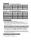
RECOMMENDED WIRING SIZES
Model No. Single (1) Phase
BC301-IT 12 AWG
BC2-IT, BC302-IT 10 AWG
Note:
1. Neutral (N) and Ground Wires to be 14 AWG Minimum.
2. Field wiring must be suitable for 75º C.
3. Use Copper wire only for all power supply connections.