


12
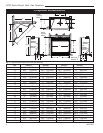
LDVT Series Direct Vent Gas Fireplace
10007852
Since it is very important that the vent-
ing system maintain its balance between
the combustion air intake and the flue
gas exhaust, certain limitations as to vent
configurations apply and must be strictly
adhered to.
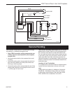
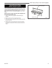
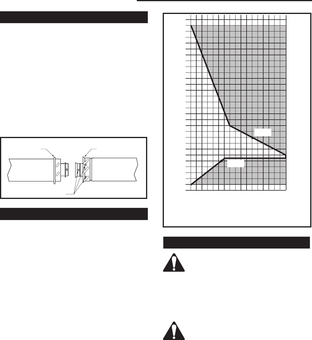
The vent graph showing the relationship between verti-
cal and horizontal side wall venting will help to deter-
mine the various dimensions allowable.
Minimum clearance between vent pipes
and combustible materials is one 1”
(25mm) on top, bottom and sides unless
otherwise noted.
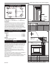
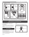
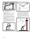
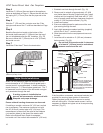
When the vent termination exits through foundations
less than 20” (508mm) below siding outcrop, the vent
pipe must flush up with the siding.
It is always best to locate the fireplace in such a way
that minimizes the number of offsets and horizontal
vent length of vent pipe from the flue collar of the fire
-
place to the face of the outer wall.
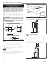
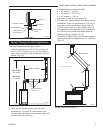
Vertical Sidewall Applications
How to Use the Vent Graph
The vent chart should be read in conjunction with the
following vent installation instructions to determine the
relationship of the vertical and horizontal dimensions of
the vent system.
1. Determine the height of the center of the horizontal
vent pipe exiting through the outer wall. Using this
dimension on the Sidewall Vent Graph. (Fig. 13)
locate the point intersecting with the slanted graph
line.
2. From the point of this intersection, draw a vertical
line to the bottom of the graph.
3. Select the indicated dimension, and position the
fireplace in accordance with same.
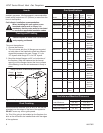
Example A:
If the vertical dimension from the floor of the fireplace
is 11’ (3.4 m) the horizontal run to the face of the outer
wall must not exceed 14’ (4.3 m).
Example B:
If the vertical dimension from the floor of the unit is 7’
(2.14 m), the horizontal run to the face of the outer wall
must not exceed 8¹⁄₂’ (2.6 m).
3
4
5
6
7
8
9
10
11
12
13
14
15
16
17
18
19
20
21
22
23
24
25
26
27
28
29
30
3 4 5 6 7 8 9 10 11 12 13 14 15 16 17 18 19 20
eg: A
eg: B
CFM102
DV Graphic
9/28/00 sta
Horizontal dimension from the outside face of the wall to
the center of the fireplace vent flange
Sidewall vent graph showing the relationship between vertical
and horizontal dimensions for a Direct Vent flue system.
Vertical dimension from the floor of the fireplace to
the center of the horizontal vent pipe
Fig. 13 Sidewall venting graph. (Dimensions in feet)
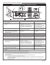
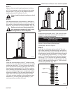
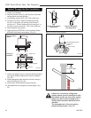
Twist Lock Pipes
When using CFM Corporation twist-lock pipe it is not
necessary to use sealant on the joints. The only areas
of the venting system that need to be sealed with high
temperature silicone sealant are the sliding joints of any
telescopic vent section used in the system.
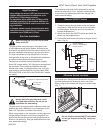
To join the twist lock pipes together, simply align the
beads of the male end with the grooves of the female
end, then while bringing the ends together, twist the
pipe until the flange on the female end contacts the
external flange on the male end. It is recommended that
you secure the joints with three (3) sheet metal screws,
however this is not mandatory with twist lock pipe.
To make it easier to assemble the joints we suggest
putting a lubricant (Vaseline or similar) on the male end
of the twist lock pipe prior to assembly.
TWL100
Twist Lock Pipe
3/12/99 djt
Male End
Female End
Screw Holes
TWL100
Fig. 12 Twist-lock pipe joints.