


16
LDVT Series Direct Vent Gas Fireplace
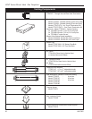
10007852
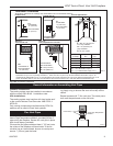
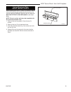
When it is not possible to meet the required vent ter-
minal clearances of 12” (305mm) above grade level a
snorkel vent kit is recommended. It allows installation
depth of down to 7” (178mm) below grade level. The 7”
is measured from the center of the horizontal vent pipe
as it penetrates through the wall.
If venting system is installed below
ground, we recommend a window well with
adequate and proper drainage.
Ensure sidewall venting clearances are observed.
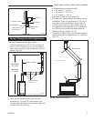
If installing a snorkel a minimum 24” (610 mm) vertical
rise is necessary. The maximum horizontal run with
the 24” (610 mm) vertical pipe is 36” (914 mm). This
measurement is taken from the collar of the fireplace
(or transition elbow) to the face of the exterior wall.
Refer to the Sidewall Vent Graph for extended
horizontal run if the vertical rise exceeds 24” (610 mm).
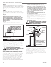
1. Establish vent hole through the wall. (Fig. 18)
2. Remove soil to a depth of approximately 16” (406
mm) below base of snorkel. Install drain pipe. Install
window well (not supplied). Refill hole with 12” (305
mm) of coarse gravel leaving a clearance of approxi-
mately 4” (102 mm) below snorkel. (Fig. 26)
3. Install vent system.
4. Ensure a watertight seal is made around the vent
pipe coming through the wall.
5. Apply high temperature sealant caulking (supplied)
around the 4” and 7 “ snorkel collars.
6. Slide the snorkel into the vent pipes and secure to
the wall.
7. Level the soil to maintain a 4” (102 mm) clearance
below snorkel. (Fig. 26)
Below Grade Installations
Do not back fill around snorkel. A clearance
of at least 4” (102 mm) must be maintained
between snorkel and the soil.
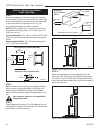
If the foundation is recessed, use recess brackets (not
supplied) for securing lower portion of the snorkel.
Fasten brackets to wall first, then secure to snorkel
with self drilling #8 x 1/2 sheet metal screws. It will be
necessary to extend vent pipes out as far as protruding
wall face. (Fig. 27)
BG402a
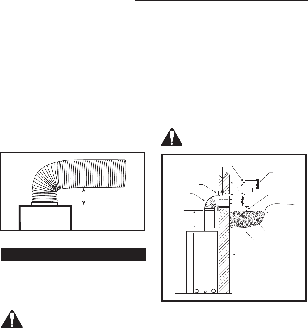
Top Vent
Below grade installation
1/26/00 djt
Firestop
7” Pipe
7TDVSNORK
(Snorkel)
4” (102mm)
Clearance
Min.
Window
Well
Gravel
Drain
BG402
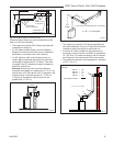
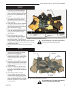
Fig. 26 Below grade installation.
Zero Clearance
Sleeve
(if required)
*A minimum of 24” (610mm) ver
-
tical pipe must be installed when
using the 7TDVSNORK Kit.
*The 22” (559mm) vertical rise
(center to center) of the snorkel
may be included for calculationof
max. horizontal run.
24” (610mm)
Minimum*
Screws
Foundation Wall
Step 4
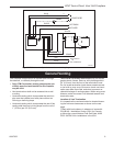
Install the 4” (102 mm) flex vent pipe to the appliance
collar as described on Page 11. Secure the end with the
first spring 6³⁄₄” (172 mm) from the flex pipe end to the
unit.
Step 5
Slide the 7” (178 mm) flex vent pipe over the 4” flex
vent pipe and secure the 7” collar as described on Page
11.
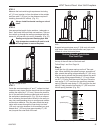
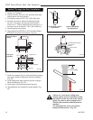
Step 6
Bend the flex pipe horizontal so the bottom of the
horizontal pipe measure 6¹⁄₂” (165mm) from the top of
the unit immediately after the 90° formation. (Fig. 25)
Be sure to follow the 1” (25mm) rise in a 24” (610mm)
horizontal run rule.
Step 7
Install the 4” flex then 7” flex to the termination.
6" (165mm)
FP1475
flex 90 bend
4/04 djt
FP1475
Fig. 25 Bend flex vent at 90° so horizontal portion is 6¹⁄₂”
(165 mm) off top of unit.