36
LDVT Series Direct Vent Gas Fireplace
10007852
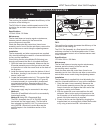
The fireplace, when installed, must be
electrically connected and grounded in
accordance with local codes or, in the
absence of local codes, with the current
CSA C22.1 Canadian Electric Code.
For USA installations follow the local
codes and the national electrical code
ANSI/NFPA No. 70.
Should this fan require servicing or repair
the power supply must be disconnected.
For rewiring of any replacement parts refer
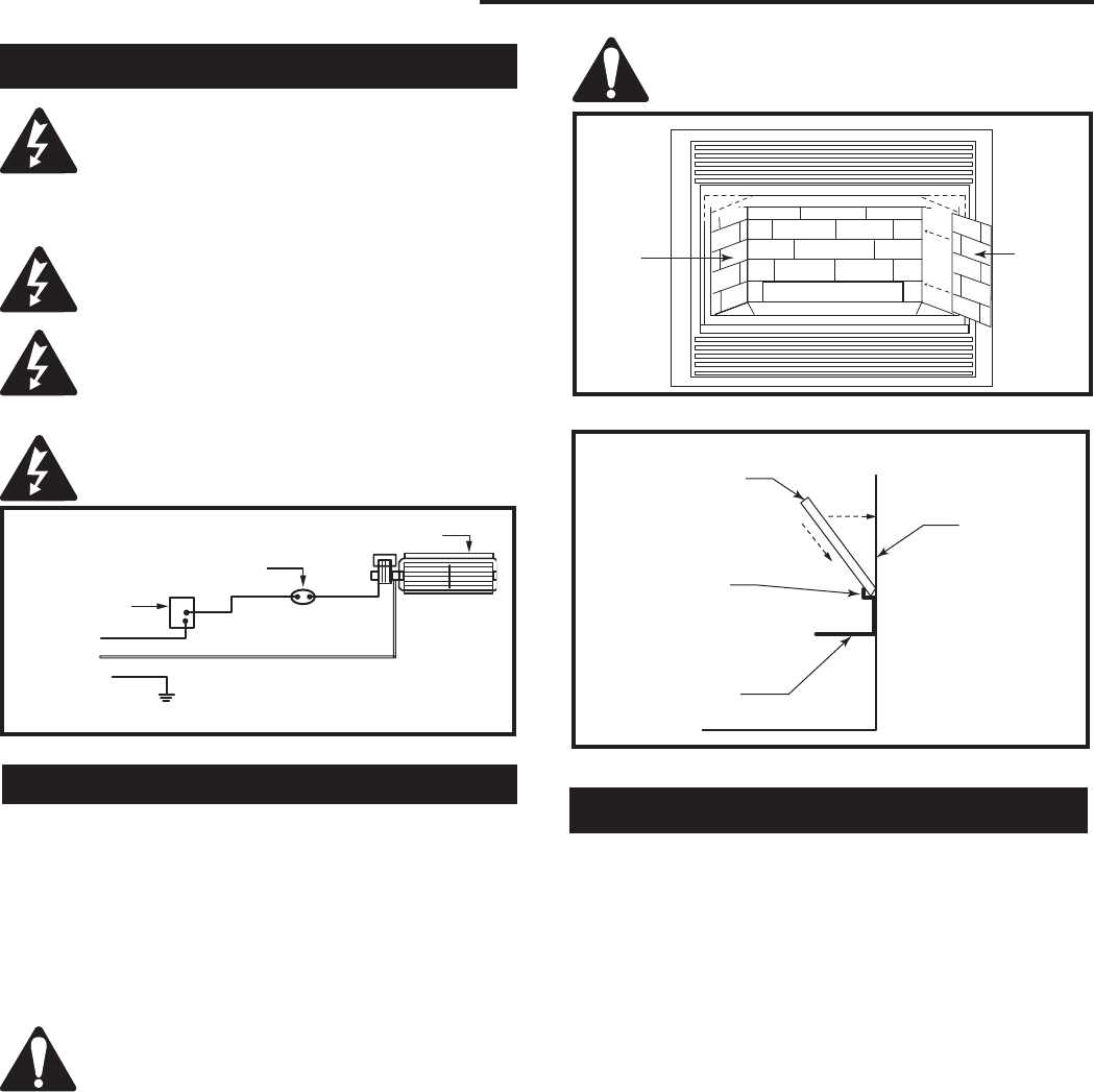
to Figure 49.
Any electrical re-wiring of this fan must be
done by a licensed electrician.
Wiring Instructions
Black
White
Ground
FP394
WIRING DIAGRAM
11/20/96
Fan
Temperature Sensor
Speed Control
FP1025
Fig. 49 FK24 fan wiring.
Ceramic refractory panels are available for the LDV
series appliances
Kit Model and Finish
Unit Sandstone Red Black Grey
33LDVT GAHC3I0 GAFC3I0 GABC3I0 GAGC3I0
36LDVT GAHC3J0 GAFC3J0 GABC3J0 GAGC3J0
39LDVT 39LDVCR
43LDVT 43LDVCR
For aesthetic purposes we recommend
lining up the horizontal mortar lines.
Ceramic Refractory Panels
Take care when handling the refractory
panels as they are fragile until held in place
and supported.
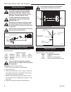
Installation, refer to Figures 50 & 51
1. Remove the front window frame assembly.
2. Remove the logs.
3. Place the rear refractory panel in place. Locate the
lower edge of the panel in the ledge formed by the
top of the rear log support bracket.
4. Slide the side refractory panels into place to hold
the rear panel secure. Repeat the procedure on the
other side.
5. Replace the logs and window frame assembly.
FP1231
Ceramic panels
11/02
Side
Panel
Side
Panel
Log Support
Burner Tray
Back Panel
FP1231
Fig. 50 Ceramic panel installation.
FP1232
rear ceramic panel
11/02
Rear Refractory
Panel
Rear Panel Sup-
port Brackets
Rear Log
Support
Firebox Back
Panel
FP1232
Fig. 51 Rear refractory panel installation.
Optional remote control units are available to control
different functions of the appliances
Model Function/s Controlled
RCI ON/OFF
RC2 ON/OFF and Temperature.
IMTFK Wall mounted thermostat control
Remote Controls


