


10
DVBR Series Direct Vent Gas Fireplace
20000584
FP1543
remove insulation
1/05
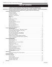
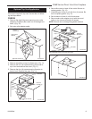
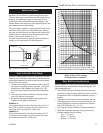
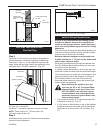
Remove Insulation
FP1543
Fig. b Remove and discard insulation.
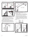
Your fireplace is approved to be vented either through
the side wall, or vertical through the roof.
• Only CFM Corporation venting components spe-
cifically approved and labelled for this fireplace
may be used.
• Venting terminals shall not be recessed into a wall or
siding.
• Horizontal venting which incorporates the twist lock
pipe must be installed on a level plane without an
inclining or declining slope.
• Horizontal venting which incorporates the use of flex
venting shall have an inclining slope from the unit of
1/2” (13 mm) per12” (305 mm).
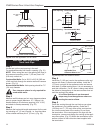
There must not be any obstruction such as bushes,
garden sheds, fences, decks or utility buildings within
24” from the front of the termination hood.
Do not locate termination hood where excessive snow
or ice build up may occur. Be sure to check vent termi-
nation area after snow falls, and clear to prevent ac-
cidental blockage of venting system. When using snow
blowers, make sure snow is not directed towards vent
termination area.
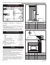
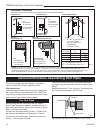
Location of Vent Termination
It is imperative the vent termination be located observ-
ing the minimum clearances as shown on the following
page.
General Venting
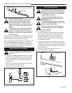
DVBR42
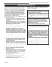
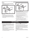
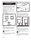
1. Remove the seven (7) screws securing the heat
shield cover plate to the fireplace. (Fig. a) Discard
the heat shield cover plate.
FP1542
DVBR42 heat shld
cover plate
1/05
Remove Screws (7)
Heat Shield
Cover Plate
FP1542
Fig. a Remove screws securing heat shield cover plate. Dis-
card cover plate.
2. Carefully remove the square piece of insulation
along the perforations. (Fig. b) Discard insulation.
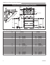
3. Remove the eight (8) screws securing outer collar
adapter to fireplace. (Be careful not to damage insu-
lation.) (Fig. 10)
4. Set outer collar adapter aside.
5. Remove insulation on top of collector box. (Fig. 11)
6. Remove the four (4) screws securing flue cover to
top of unit and remove flue cover. (Fig. 11)
7. Remove the four (4) screws securing flue pipe to
back of unit. Remove flue pipe. (Fig. 11)
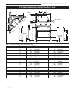
8. Secure flue cover to back of flue outlet. Be sure to
replace gasket. (Fig. 12)
9. Install flue pipe to top of unit with four (4) screws. Be
sure to replace gasket. (Fig. 12)
10. Set insulation in back of unit foil side down.
11. Secure outer collar adapter to unit with the round
collar on top, secure with eight (8) screws.
NOTE: Be sure not to damage any gasket material.