


25
DVBR Series Direct Vent Gas Fireplace
20000584
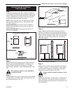
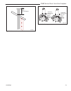
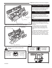
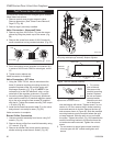
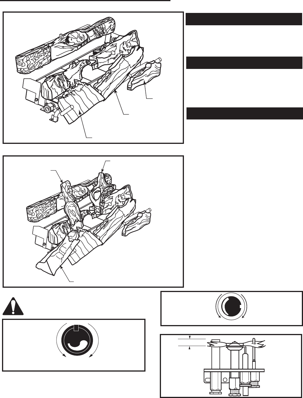
Right Cover
Log
Center Log
Left Cover Log
LG391
Fig. 52 Place Left and Right Cover Logs and Center Log on grate.
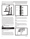
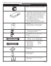
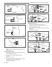
Log Top Right
(DVBR42 ONLY)
Left Cross Log
Left Front Log
LG392
Fig. 53 Place Left Front Log, Left Cross Log and Log Top Right.
Top logs must be placed properly onto
notches.
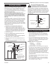
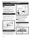
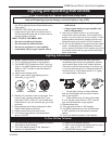
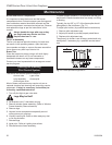
Flame & Temperature Adjustment
For fireplaces equipped with Hi/Lo valves,
flame adjustment is accomplished by rotating
the Hi/Lo adjustment knob located near the
centre of the gas control. (Fig. 54 & 55)
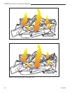
Flame Characteristics
It is important to periodically perform a visual
check of the pilot and the burner flames.
Compare them to Figures 56, 57 & 58. If any
of the flames appear abnormal call a service
person.
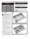
Inspecting the Venting System
This appliance venting system was designed
and constructed to develop a positive flow
adequate to remove flue gases to the outside
atmosphere.
Any foreign objects in the venting system,
except those designed specifically for the
venting system, may cause spillage of flue
gases.
To inspect the venting system, make sure the
main gas valve is off. Remove glass frame
(See Glass Frame Removal Section). Using
a flashlight, check the area above the baffle
in the combustion dome. Clean if necessary.
L
O
H
I
FP390
FLAME ADJUSTMENT KNOB
11/21/96
Turn
counterclockwise
to increase
flame height
Turn clockwise
to decrease
flame height
Fig. 55 flame adjustment knob for SIT valve.
Fig. 54 Flame adjustment knob for Honeywell valve.
Turn
counterclockwise
to decrease
flame height
Turn clockwise
to increase
flame height
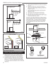
HV102
Honeywell hi/lo knob
4/5/99 djt
HV102
3/8” - 1/2”
Fig. 56 Correct pilot flame appearance.