


5
10003929
Do not use this appliance if any part of it has
been under water. Immediately call a quali-
fied service technician to inspect the unit
and replace any part of the control which has
been under water.
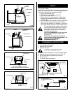
When purging the gas line, the front
glass must be removed.
The gas pipeline can be brought into the fireplace base
from the right side. It is most convenient to install it
from the right side into the valve.
When using copper or flex connector use
only approved fittings. Always provide a
union when using black iron pipe so that gas
line can be easily disconnected for burner or
fan servicing. See gas specification for
pressure details and ratings.
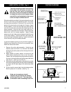
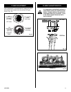
The gas line connection can be made of either properly
tinned 3/8" copper pipe, 3/8" rigid pipe or an approved flex
connector.
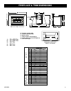
The gas control inlet is 3/8" N.P.T. therefore the 1/2" rigid
gas line must be reduced to 3/8" N.P.T. Typical installation
layout for rigid pipe is shown following. (Fig. 1)
Fig. 1
During any pressure testing of the gas line system, when
the test pressures are to exceed 1/2 psi (3.5 kpa) the
fireplace and its gas valve must not be connected to that
system.
At test pressures equal to or less than 1/2 psi, the gas valve
of the fireplace may be connected to the gas line, but must
be in the closed position.
Since some municipalities have some additional local
codes, it is always best to consult your local authority and
the CSA- B149 (.1 or .2) installation code in Canada.
FOR U.S.A Installations consult the current National
Fuel Gas Code, ANSI Z223.1
Always check for gas leaks with a mild
soap and water solution. Do not use an
open flame for leak testing.
1/2" GAS SUPPLY
1/2" X 3/8" REDUCER
3/8" NIPPLE
3/8" NIPPLE
3/8" NIPPLE
3/8" X 3/8" SHUT OFF VALVE
3/8" UNION
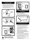
PREPARATION
Before beginning, remove glass door and logs from unit.
Also check to make sure there is no hidden damage to the
unit. Take a minute and plan out the gas,venting and
electrical route. It is best to start with the gas line first
followed by the chimney liner (See page 9).
GAS SPECIFICATIONS
MAX. MIN.
INPUT INPUT
MODEL FUEL GAS CONTROL B.T.U.H B.T.U.H.
RHEDV32RP Propane Gas Millivolt Hi/Lo 27,000 20,250
ANSI.Z21.88b-1999 / CSA 2.33b - M99
Vented Gas Fireplace Heaters
All Irving Oil gas inserts are approved
for installation in solid fuel burning
masonry or zero clearance fireplaces.
This appliance may be installed in an aftermaket
permanently located, manufactured (mobile) home,
where not prohibited by local codes.
This appliance is only for use with the type of gas
indicated on the rating plate. This appliance is not
convertible for use with other gases, unless an
available certified kit is used.
GAS INLET & MANIFOLD PRESSURES
LP (Propane)
Input Minimum 11" wc
Input Maximum 13" wc
Manifold Pressure 10" wc
IRHEDV32
CERTIFIED TO:
GAS LINE INSTALLATIONGAS
Input ratings are shown in BTU per hour and are
certified without deration for elevations up to
4,500 feet (1,370 m) above sea level.
For elevations above 4,500 feet (1,370 m) in USA,
installations must be in accordance with the
current ANSI Z223.1 and/or local codes having
jurisdiction.
In Canada, please consult provincial and/or local
authorities having jurisdiction for installations at
elevations above 4,500 feet (1,370 m).
CFM186