


8
10003929
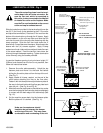
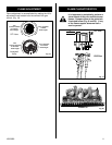
FLUE COLLAR PLATE
MOVE
BACK
CABINET TOP
FIG .4
FASTENER PLATE
MAKE SURE THE FLUE COLLAR PLATE IS IN
CONTACT WITH THE BACK EDGE OF THE CABINET TOP
PLATE FLUE COLLAR
CABINET TOP
FIG.5
FASTENER PLATE
MACHINE SCREW AFTER
FASTENED
Fig. 8
Fig. 9
Fig. 10
Fig. 11
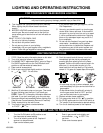
FAN KIT
Should this fan require servicing, the
power supply must be disconnected. For
rewiring of any replacement
components see Fig. 13.
FAN REMOVAL INSTRUCTIONS
1. Turn off gas and electricity.
2. Remove the front glass.
3. Remove the logs.
CAUTION: LOGS MAY BE HOT
4. Remove burner assembly and rear log support plate.
5. Remove the fan mounting nuts (2 nuts). (Fig. 12)
6. Slip off the electrical connector at the motor.
7. Lift out the fan.
8. To reinstall reverse procedure.
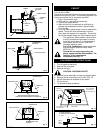
TOP VIEW
Valve
Fan speed control/
Junction box
Thermal sensor
is attached
to burner base
Fan is installed
at the back of
the air intake box
screw studs
C
B
A
Black
White
Ground
A: SPEED CONTROL
B: TEMPERATURE SENSOR
C: FAN
Fig. 12
115 volt, 60 Hz.56W
The fan kit includes the following: fan, temperature sensor,
speed control and a 6 ft. cord. The following explains how
to start and set the fan for automatic operation.
1. Plug in the electrical cord.
2. Start gas fire - see lighting procedures.
3. Turn on fan speed control.
4. Wait until the unit has warmed up sufficiently to
activate the termperature sensor, approximately
5-10 minutes.
5. Once fan starts, adjust speed control to desired fan
speed. The fan will now automatically come on
every time the fireplace is in operation. Should the
fan not be needed simply turn off the speed control.
The appliance, when installed must be elec-
trically connected and grounded in accord-
ance with local codes or, in the absence of
local codes, with the current CSA C22.1
Canadian electrical code.
For U.S.A. Installations, follow local codes
and the National Electrical code, ANSI/
NFPA No. 70.
Fig. 13
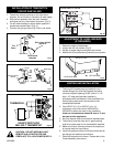
CLAMPS & SCREW
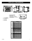
FIG.2
DAMPER
FLUE COLLAR
PLATE
3" FLEX VENT
TWO PIECES
FASTENER
PLATE
GASKET
UNIT
CLAMPS & SCREW
FLUE COLLAR PLATE
FRONT FRAME
DAMPER
UNIT
3" CHIMNEY LINER
TWO PIECES
FIG.3