


23
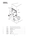
GENERAL
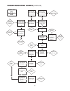
1. To turn the unit on, turn the switch to the on
position.
■ Power is sent to primary side of the
120vac/16vac transformer.
■ Power is sent to the normally closed high limit.
■ From the high limit power is sent to the normally
open contacts of the 12VDC relay and the L1 and
L2 terminals of the ignition module.
2. From the secondary of the transformer 16VAC is
sent to the controller.
■ Power is sent to the red LED (low water indicator
light) from terminal 4 of the controller.
■ If the water probe is grounded through water the
LED will go off.
■ If the water probe is not grounded the LED will
remain on and the unit will not heat.
■ If the resistance of the thermistor is higher than
the setting of the potentiometer( the unit is calling
for heat) then 16VDC is sent to the coil of the relay
and the green LED (heat indicator light)
■ The 12VDC relay will close until the unit reaches
temperature
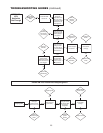
3. With the contacts of the relay closed, 120VAC is
sent to the blower and primary coil of the
120VAC/24VAC transformer.
■ From the secondary of the 24VAC transformer
power is sent to the normally open contacts of the
air switch.
■ When the air from the blower closes the air
switch, 24VAC is sent to the Th terminal of the
ignition module.
4. With both 120VAC (at L1 and L2) and 24VAC (at
Gnd and Th) to the ignition module then 120VAC
will be sent to the surface igniter.
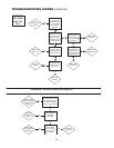
5. After the ignition module has been energized for 24
seconds the module will send 24VAC to the gas
valve.
■ The gas will touch the hot igniter and ignite.
■ The kettle will build pressure until the controller is
satisfied by the thermistor at the setting of the
potentiometer.
■ The controller will then turn off the heat circuit
until the temperature of the kettle is below the
setting
TROUBLESHOOTING GUIDES
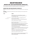
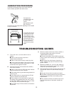
LUBRICATION PROCEDURE
Lubricate the following parts every three months to
insure smooth operation and reduce wear.
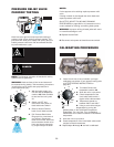
TRUNNION
HOUSING,
WORM SCREW
AND TILT GEAR
These parts are
accessed through the
top cover of the
console.
Apply grease to gear
teeth. Check for
excessive play and adjust with adjusting screw located
on top of cross bar.
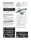
KETTLE
TRUNNIONS
On the left hand side of
the kettle there are two
grease nipples on the
top back portion of the
trunnion housing. On the
right hand side of the
kettle you must remove
the console cover to
access the two grease
nipples.
Trunnion Housing
Grease Nipple