


4
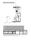
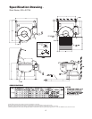
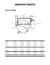
Specification Drawing -
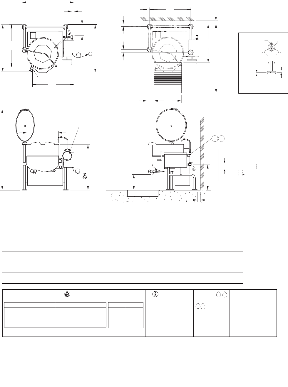
Tilting, KGL-40-T, KGL-60-T, KGL-80-T
NOTES:
Cleveland Range reserves right of design improvement or modification, as warranted.
Many regional, state and local codes exist and it is the responsibility of the owner and installer to comply with the codes.
Installation of backflow preventers, vacuum breakers and other specific codr requirements is the responsibility of the owner and installer.
Cleveland Range equipment is built to comply with applicable standards for manufacturers.Included among those approval agencies are U.L., A.G.A., NSF, ASME/N.Bd., CSA, CGA, ETL and others.
1/2" dia. Soft
Copper
Tubing (each)
When ordered
with optional
faucet.
WATERELECTRIC
120V-1 Phase, 60 Hz, 10
amps
GAS CLEARANCE
H
RIGHT = 0"
LEFT = 0"
REAR = 3"
Allow 6" space minimum
from rear and sides when
located near combustible
walls.12" recommended on
right side for service
NATURAL PROPANE
Piping: 3/4" N.P.T. Piping: 3/4" N.P.T.
Supply pressure: Supply pressure:
4.00" W.C. minimum 4.00" W.C. minimum
14.00" W.C. maximum 14.00" W.C. maximum
Manufacturer must be notified if unit will be operated above 2,000 ft. altitude.
C
B.T.U. RATING
40 gal. 140,000
60 gal.
80 gal. 190,000
100 gal.
H
C
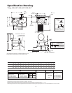
DIMENSIONS
GALS./
LITERS ABCDEFGHJKLMNOPQS I.D.
40 IN 45 3/4 42 1/2 38 35 9 42 1/4 71 40 1/2 15 1/2 23 1/4 19 35 3/4 4 3/8 24 33 63 26
150 mm 1163 108 966 889 229 1074 1804 1029 394 591 483 909 112 610 839 1601 661
60 IN 49 3/8 46 41 1/2 37 11 3/4 47 1/4 75 43 3/4 15 1/4 24 1/2 22 39 3/8 6 28 37 68 29 1/2
225 mm 1255 1169 1055 940 299 1201 1905 1112 388 623 559 1001 153 712 940 1728 750
80 IN 53 49 44 1/2 39 14 3/4 51 78 44 3/4 14 25 25 43 7 30 40 72 33
300 mm 1347 1245 1131 991 375 1296 1982 1137 356 635 635 1093 178 762 1016 1829 839
J
K
C
H
N
O
M
L
Q
P
3"
(77 mm)
REF
S I.D.
C
B
A
G
HANDWHEEL REPLACED
BY SWITCH FOR
POWER TILT OPTION
H
F
E
D
2 1/4"
(57 mm)
REF
2 1/2"
(64 mm)
2 1/2"
(64 mm)
4 1/8"
(105 mm)
3" (77 mm)
MIN.
CLEARANCE
UNIT SHOWN WITH OPTIONAL 2" TANGENT DRAW-OFF VALVE,
SPRING ASSIST COVER AND HOT & COLD WATER FAUCET.
9/16"
14
mm
120º
TYP
1" (25
mm)
MAX. ADJUSTMENT
1 5/8" (42
mm)
Ø
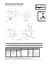
FLANGED FOOT DETAIL
7/16" (11
mm)
Ø
3 HOLES ON
3 1/8" (80
mm)
Ø
B.C.D.
4 7/8"
124
Ø
mm
RECOMMENDED
FLOOR SLOPE
1" (26 mm) per 4' (1220 mm)
PIPE DRAIN RECOMMENDED
min. valve size plus 1" (26 mm)
4" (102 mm)
RECOMMENDED
VALVE OPENING