


Operator’s Manual P/N-260APC-A
______________________________________________________________________________
12
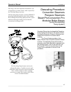
Detail Procedure- Using the Descaling Pump System
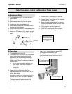
A. Equipment Setup
1. Turn the Steamer OFF; the boiler will drain
automatically
2. Open the door at the base of the unit
3. Remove the hand-hole plate and gasket.
Discard old gasket.
4. Inspect the boiler for scale build up.
5. Remove any loose scale within reach that is
around the hand-hole plate.
6. Install Hand-Hole plate with the descaler ports.
And a new gasket.
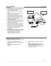
7. Attach the 3” Feed and Drain nipples with the
attached unions to the INLET and OUTLET
ports.
1. Connect the ½” Feed Hose with attached
union to the bottom of the 3” nipple.
2. Connect the ¾” Drain Hose with the attached
union to the top 3” nipple.
3. Make sure both Feed and Drain Valves are
closed. Drop the open end of the Drain Hose
into the reservoir pail.
4. Fill the reservoir pail with 5 gallons of
DISSOLVE descaling liquid.
5. Lower the Pump into the descaling liquid.
Proceed to Part B, descaling.
B. Descaling
1. Turn the Steamer power ON.
2. Turn the Pump ON and open the Feed Hose
Valve to the boiler. Let the boiler fill with
descaler to just above the top of the Sight
Glass before opening the Drain Hose Valve.
Make sure the Drain Line Hose is in the pail
with the pump.
• Do not allow the liquid to fall below the
pump intake. Water may be added to
reservoir pail to keep pump intake
submerged.
• Watch for liquid at the sight glass
3. Open the Drain Hose Valve when the
descaler reaches the level just above the to
of the Sight Glass.
4. While the descaler solution is
circulating, keep an eye on the liquid level in
the pail. Do not allow the level to fall below
the pump intake or to overflow in the pail.
The required level can be maintained by
controlling the flow with the Feed Hose Valve
5. Let the pump circulate descaler for 1 hour.
6. After 1 hour, turn the Steamer power OFF;
the boiler will automatically drain.
7. Turn OFF the pump; close both the Drain
and Feed Hose Valves. Proceed to Part C,
Flushing.
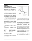
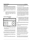
Hand-Hole Plate with
Descaler Ports for
Feed and Drain Hoses.
Sight Glass located on
Left.
½” Feed Hose and
Control Valve-Bottom
¾” Drain Hose and
Control Valve-Top