


Operator’s Manual P/N-260APC-A
______________________________________________________________________________
4
INSTALLATION SAFETY
WARNING
Qualified installation personnel, working to all applicable
local and national codes must accomplish installation of
this equipment. Improper installation of this product could
cause or damage.
Do not store or use gasoline or other flammable Vapors
and liquids in the vicinity of this or any other appliance.
The flooring that will be directly under the boiler must also
be made of a noncombustible material.
Cleveland Range equipment is designed and built to com-
ply with applicable standards for manufacturers. Included
among those certification agencies which have approved
the safety of the equipment design and construction:
UL, A.G.A., NSF ASME, CSA, CGA, and others.
Cleveland Range equipment is designed and certified for
safe operation only when permanently installed in accor-
dance with local and I or national codes. Many local codes
exist and it is the responsibility of the owner and installer
to comply with these codes
In no event shall Cleveland Range assume any liability for
consequential damage or injury resulting from installations
which is not in strict compliance with our installation
instructions. Specifically, Cleveland Range will not
assume any liability for damage resulting from improper
installation of equipment including, but not limited to,
temporary or mobile installations
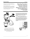
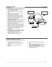
INSTALLATION INSTRUCTIONS
1. These instructions must be retained by the owner/user
for future reference. Gas-fired boilers are only to be in-
stalled in noncombustible areas that have provisions for
adequate air supply. The term "boiler’
s
will be used syn-
onymously with "steam generator".
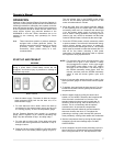
2. Position: For proper operation and drainage, the equip-
ment must be level. It should be placed next to an open
floor drain. DO NOT POSITION THE UNIT DIRECTLY
ABOVE WE FLOOR DRAIN. Observe all clearance re-
quirements to provide air supply for proper operation,
as well as sufficient clearance for servicing. The
surrounding area must be free and clear of
combustibles. Dimensions and clearance specifications
are shown on the specification sheet.
3. Install in accordance with local codes and/or the Na-
tional Electric Code ANSI/NFPA No.70-1987.
Installation in Canada must be in accordance with
Canadian Electrical Code CSA Standard C22.1. The
installer A wiring diagram is provided inside the
base cabinet must ground equipment that is
connected to electricity.
WARNING
INJURY TO PERSONNEL AND EQUIPMENT DAMAGE
May result from an improper drain connection. No
connection lines are to be under the unit
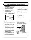
4. Drain Line. The drain line outlet discharges exhaust
steam and hot condensate. Connect 1-1/2-inch IPS
piping (or larger) to extend the drain line to a nearby
open floor drain. Up to two elbows and six feet of 1-1/2-
inch IFS (or larger) extension pipe should be connected
to the drain termination. No more than two pieces of
Cleveland Range Equipment should be connected to
one common drain line. The extension piping must have
a gravity flow and vent freely to the air. This drain outlet
must be free-vented to avoid the creation of
backpressure in the steamer cooking compartments. To
ensure a vented drain line, DO NOT UNDER ANY
CIRCUMSTANCES, CONNECT THE DRAIN OUTLET
DIRECTLY TO THE FLOOR DRAIN OR SEWER LINE.
Do not run the drain line discharge into PVC drain
piping or any other drain piping material not capable of
sustaining 180' F operation.
5. Water Supply. Connect COLD water plumbing to the
line strainer (Never conned hot water to the condensate
water fill line strainer) Constant flow pressure must be
maintained between 35 and 60 psi, and not experience
a pressure drop below 35 psi when other appliances
are used. If the water pressure exceeds 60 psi, a
pressure-reducing valve must be installed in the water
supply plumbing to reduce the water pressure to less
than 60 psi. Locations and pressure data are shown on
the specification sheet. 3/S-inch IPS plumbing is
sufficient for water supply lines up to 20 feet in length,
but water supply lines longer than 20 feet should be at
least 1/2-inch IPS. Flush water supply lines thoroughly
before connecting them to the unit. Use water, which is
low in total dissolved solids content and low in gas
content to prevent internal scaling, pitting and corrosion
of the steam generator, and carry-over of minerals into
the steam. Water, which is fit to drink, can still contain
highly detrimental impurities.
NOTE: If equipped with a kettle and kettle water fill
swing spout, 3/8-inch (10 mm) hot and/or
cold-water connection(s) will be required at
the swing spout valve.
6. Turn on the cold water supply to the unit Ensure that
the manual water valve, inside the base cabinet is
open.
7. Fuel Supply. Connect the primary fuel supply in accor-
dance with the following instructions. Location and other
data are shown on the specification sheet.
For Gas-Fired Steam Generators: Post in a prominent
location, instructions to be followed in the event the user
smells gas. This information shall be obtained by the
consulting the local gas supplier.