


Getting Started
2.2. Receiving and Installation
The dishwasher is shipped from the factory in a corrugated box on a wooden pallet. The
installation guidelines give a systematic procedure for setting up the machine.
Start by removing the dishmachine from the box. Remove the packaging, unwrap the machine and
check for the following components:
Scrap Accumulator complete with lid and scrap tray.
Inside the wash tank is a box with one control box key, 4 legs, thermometer, spray
arms, machine manual and a cam timer wrench.
Tube Stiffeners: The tube stiffeners must be used to prevent the feed tubes from
curling up inside the chemical pail allowing the tip to rise out of the chemical. Remove
the tie-wraps securing the tube stiffeners to the dishmachine to free them up for use.
Be careful not to remove any of the tie-wraps securing the tube bundle. Red is for
detergent, white for sanitizer, and blue for rinse aid.
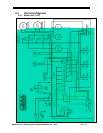
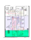
2.2.1. Electrical
*
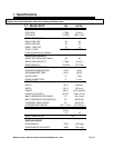
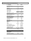
A 20-amp, 115 volt, 60 Hz dedicated circuit must be used to supply electrical power to the model
AH and model C Dishmachines (see model AH specifications on page
3 and model C specifications
on page
5). A 30-amp, 115 volt, 60 Hz dedicated circuit must be used to supply electrical power to
the model B Dishmachine (see model B specifications on page XX4).
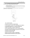
2.2.2. Plumbing
*
The water supply connection is made with a ¾” hot water line to the water supply inlet on the top of
the machine. The water supplied to the machine is recommended to be 140° F (120° F minimum).
Caution: Do not connect galvanized pipe water supply to dishmachine. This will create electrolysis,
causing corrosion.
Technical personnel are available during normal business hours at CMA Headquarters should you,
as an installer, have any questions please call 800-854-6417.
*
Electrical and plumbing connections must be made by a qualified service person who will comply
with all available Federal, State, and Local Health, Electrical, Plumbing and Safety codes
MODEL AH, B & C INSTALLATION & OPERATION MANUAL Rev. 1.00A Page
8