


Any spare cable must be coiled either behind the oven (not more than 30cm above the base
of the oven recess) or pushed into the air gap below the oven after installation.
Where a hob is fitted adjacent to or above an oven a 30 amp or 45 amp double pole switch
with a minimum contact clearance of 3mm should be used to feed both units via separate
suitably rated cables.
Where a hob unit is fitted above the oven unit we recommend that 85
o
C High Temperature
PVC with insulated 3 core flexible cord to table 15 of BS 6141:1991 with a conductor size of
2.5mm
2
must be used to connect the hob to the control unit.
Where a hob unit is fitted adjacent to the oven unit, then 4mm
2
twin and earth cable to BS
6004 is recommended to connect the hob unit to the control unit.
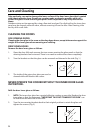
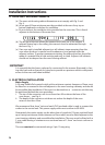
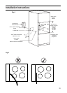
In all cases adhere to routing details (see fig. 5).
Your cooker should have been checked to ensure that the voltage corresponds with your
supply voltage, this is stated on the rating plate which is located on the oven front frame
(lower).
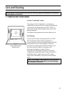
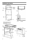
(a) The oven unit should be placed on the floor on its carton base in front of the
housing cabinet. The rear of the unit should be in line with the conduit box.
(b) Ensure there is sufficient cable for any future servicing.
(c) Remove the terminal cover. Prepare the cable, pass it through the cable
entry hole in the oven rear panel and fit to terminal block. Secure the cable clamp and
replace the terminal cover.
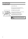
(a) Using a spirit level, check that the housing cabinet is level from side to side and
from front to back in its installed position.
(b) Correct any unevenness by placing spacers under the bottom of the cabinet. Make sure
that the cabinet rests firmly on the floor without rocking.
(c) Before the oven is fitted the cabinet must be firmly secured to the backing wall
for stability.
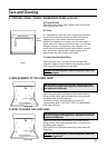
(d) The oven unit should now be lifted (this requires two people) into the cabinet
and pushed fully home.
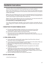
(e) Finally the oven unit must be secured to the cabinet. Position the oven side trims
equally about the cabinet sides. This should give an overlap of approx. 1.5mm per
side (see Fig. 2). Secure the oven unit to the cabinet, through the side trims, by means
of the four screws provided, two each side trim.
(f) Remove all packing material from the grill and oven interior.
4 x No.6 Pozi Head screws
CONDUIT BOX TO MAINS TERMINAL BLOCK
4. FINAL INSTALLATION
LIST OF LOOSE ITEMS
27
Installation Instructions