


Page 24
IQ Mixer/Multiplexer Hardware Installation
Rev. 0
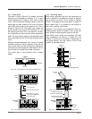
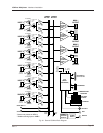
6.2.3 D/A Converter
To set channel gain levels, a digital-to-analog con-
verter continuously converts all gain settings to
control voltages. An analog demultiplexer sends the
appropriate control voltages to each of the twelve
VCAs.
6.2.4 Log Amp and A/D Converter
The A/D converter scans through an eight-channel
multiplexer to read the input and output signal lev-
els. When a channel is selected, the signal is sent
through a logarithmic amplifier for increased dy-
namic range. This analog voltage is then converted
to a binary number that the microprocessor can
read. The processor can then mathematically in-
crease detector time constants, perform averaging
or other response functions.
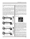
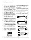
6.2.5 Auxiliary Port
Auxiliary devices such as supplemental cooling
fans can be remotely controlled via the AUX output
on the unit. When the auxiliary control feature is
turned on by the host computer, 10 VDC is supplied
across pin 3 and pin 1 (ground) of the male 3-pin
AUX connector. This port can control solid state
relays, and since it has a current-limit resistor (16
mA max.), it can directly drive an LED or opto-
coupler.
The AUX input function is used by applying a 5-30
VDC signal to pin 2 (with pin 1 as ground). A high or
low signal here will be communicated to the host
computer. A logic low can be less than 0 volts
(negative); the signal is internally clamped for cir-
cuit protection.