Page 9
IQ Mixer/Multiplexer Hardware Installation
Rev. 0
optional shield for the Crown Bus cable. Only the
shield of the input cable should be connected.
Shielded wire will reduce the total distance a Crown
Bus loop can be run, but shielding may be neces-
sary to reduce interference with certain kinds of
audio cables. (Section 3.2)
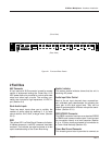
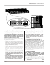
Crown Bus Input/Output Connector
A 4-pin removable barrier block plug is used for
input and output connection to the Crown Bus. The
pins are numbered backward from right to left (as
you face the back panel of the unit). Pin 1 is input
negative (–), pin 2 is input positive (+), pin 3 is
output negative (–), and pin 4 is output positive (+).
(Section 3.2)
Main Audio Outputs
A 3-pin removable barrier block plug is used to
connect to the main output of each channel. These
outputs can also be connected to the stack inputs
(B) of other mixer/multiplexers to make a 12x2 (or
larger) mixer. (Section 3.3.2)
Auxiliary Bus Audio Outputs
A 3-pin removable barrier block plug is used to
connect to the bus audio output of each channel.
The bus outputs are isolated switchable outputs that
can be turned on when needed by the
IQ System
.
This allows many multiplexers to be tied together on
the same bus without loading down the outputs.
(Section 3.3.2)
Audio Inputs
A 3-pin removable barrier block plug is used to
connect to the input of each of the six audio inputs.
The input gain control (E) and the input selector (K)
of each one should be set to match the input signal
level. These inputs can also be connected in parallel
with the inputs of other mixer/multiplexers to make a
6x4 (or larger) mixer. (Section 3.3.1)
Input Selector
A three-position input selector accommodates dif-
ferent input signal levels. The three settings are L
for line-level input, M for mic-level input, and P for
mic-level input with phantom power. The P setting
supplies 44 volts DC for phantom-powered mics.
IQ Address
An 8-section DIP switch is used to set the IQ ad-
dress of the unit. The unit must be given a unique IQ
address so it can be independently controlled and
monitored by a the system. It must also be set
properly if the unit
is to be used in a Crown Local
Net. Two or more IQ components of the same type
should NEVER have the same address on the same
Crown Bus loop. (Section 3.2) Important: The IQ
address should only be set with the power cord
disconnected from the AC supply.
Baud Rate & Parity
A 6-section DIP switch is used to set the
baud rate
and parity for RS232/RS422 serial communication.
This is only necessary when the DB25 connector (F)
is used. Important: The baud rate should only be set
with the power cord disconnected from the AC sup-
ply.
Communication Standard
A communication standard switch which allows the
unit to be configured for the RS232 or RS422 com-
munications. (Sections 3.1³3.1.1) Important: The
communication standard should only be set with the
power cord disconnected from the AC supply.
Important:
TURN THE UNIT OFF before connecting to the RS232/RS422 (F) or Crown Bus
(H) connectors. TURN THE UNIT OFF before changing the settings of the IQ Address (M),
Baud Rate & Parity (N) or Communication Standard (O) switches.


