Page 5
IQ Mixer/Multiplexer Hardware Installation
Rev. 0
ILLUSTRATIONS
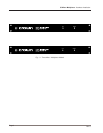
1.1 Three Mixer / Multiplexer Models ............................ 6
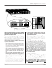
2.1 Front and Rear Panels .............................................. 8
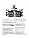
3.1 An
IQ System
with a PC Host Computer, etc. ........10
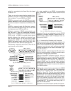
3.2 RS232 Cable Wiring for a PC ..................................11
3.3 RS422 Cable Wiring for a Macintosh ......................11
3.4 RS232 Cable Wiring for a Macintosh ......................11
3.5 Selecting the Communication Parameters ..............12
3.6 Crown Bus Wiring for Removable Barrier Blocks...13
3.7 Crown Bus Wiring for 5-pin DIN Input ....................14
3.8 Crown Bus Wiring for 4-pin DIN Output .................14
3.9 Crown Bus Wiring Loopš from Output to Input, etc.14
3.10 An Audio Input Section ............................................15
3.11 Suggested Audio Input Gain Control Settings ........15
3.12 Balanced Audio Input Wiring...................................15
3.13 Unbalanced Audio Input Wiring ..............................16
3.14 Sensing Input Section..............................................16
3.15 An Audio Output Section .........................................17
3.16 Balanced Audio Output Connections
......................
17
3.17 Unbalanced Audio Output Connections
..................
17
3.18 A 12x2 Mixer Using 2 Mixer/Multiplexers
...............
17
3.19 Stacking the Outputs of Multiple Units ...................18
3.20 A 6x8 Mixer Using 4 Mixer/Multiplexers.................18
3.21 Paralleling the Inputs of Multiple
Units
...................
18
3.22 A 12x8 Mixer Using 8 Mixer/Multiplexers
...............
18
3.23 Sample Auxiliary System Wiring
.............................
19
3.24 Internal Auxiliary Circuit
..........................................
19
4.1 A Crown Local Net RS422 Serial Loop
....................
20
4.2 Crown Local Net Wiring
...........................................
21
6.1 General IQ Mixer Block Diagram
............................
25
A.1 IQ Address Switch Settings from 0 to 125..............27
A.2 IQ Address Switch Settings from 126 to 250 ..........28


