


Page 15
IQ Mixer/Multiplexer Hardware Installation
Rev. 0
added to the audio lines. Use only the signal
lines which normally connect to pins 2 and 3 of
the XLRs.
Note: Because typical mic cables
have high capacitance, the maximum possible
Crown Bus loop distance will be less.
Outside RF interference is seldom a problem for a
Crown Bus loop…especially if shielded twisted-pair
wire is used. However, there are extreme situations
when fiber optic wiring is recommended. For ex-
ample, locating a Crown Bus loop next to an AM
radio transmission line may require fiber optic ca-
bling. An extremely long Crown Bus loop distance
(greater than 10 miles) may also require fiber optic
cabling.
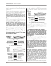
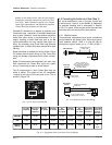
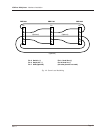
Some examples of twisted pair wiring follow. Figure
3.6 shows point-to-point wiring for the Crown Bus
using two female removable barrier block connec-
tors:
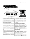
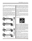
Some IQ components use separate 5-pin and 4-pin
DIN connectors for Crown Bus input and output
wiring. Connecting to them is shown below:
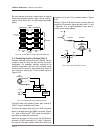
The IQ components in each Crown Bus loop are
wired in series. The output of one IQ component
÷loopsš to the input of the next and so on. This is
shown in Figure 3.9.
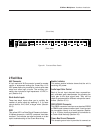
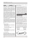
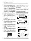
Fig. 3.10 An Audio Input Section
Pro audio
equipment
Semi-pro or
consumer
equipment
Dynamic
mic, speech
Condenser
mic, speech
Hot
condenser
mic, speech
Dynamic
mic, music
Hot
condensor
mic, music
Close-miked
dynamic mic,
bass/drums
Close-miked
dynamic mic,
kick drum,
guitar amp
dBm/dBV
dBu
Suggested
Setting
+4 dBm
+4 dBu
–4 (L)
–10 dBV
–8 dBu
+8 (L)
–75 dBV
–73 dBu
+21 (M)
–65 dBV
–63 dBu
+11 (P)
–45 dBV
–43 dBu
+18 (P)
–55 dBV
–53 dBu
+21 (M)
–25 dBV
–23 dBu
–2 (P)
–15 dBV
–13 dBu
–12 (M)
–5 dBV
–3 dBu
–12 (M)
or
+3 (L)
0 dBm = 0.775 VRMS with a 600 ohm load, 0 dBV = 1 VRMS, 0 dBu = 0.775 VRMS
Fig. 3.11 Suggested Audio Input Gain Control Settings
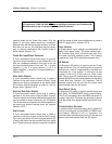
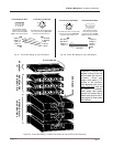
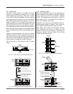
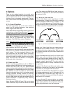
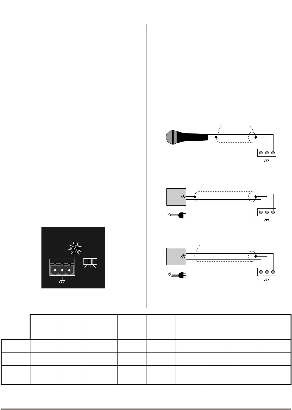
Fig. 3.12 Balanced Audio Input Wiring
+–
Shield connected
at both ends
INPUT
+
–
2-wire line cord
(or battery power)
Output
Note: If more than one
input is driven from the same
source equipment, connect only
one shield at the source
equipment chassis.
Microphone
INPUT
Floating
source
+
–
3-wire grounded line cord
(or other ground connection)
Output
Shield not connected
at this end
INPUT
Grounded
source
+–
+–
+–
AUDIO
IN
1
LMP
0
-5
-10
-12
5
10
15
21
ADD 25
FOR MIC
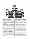
3.3 Connecting the Audio Ins & Outs (Step 3)
IQ mixer/multiplexers have 6 mic/line inputs and
2 stack inputs. (Input 6 of the
AMB-5
is dedicated
for ambient sensing and is discussed in Section
3.3.2.) For output, there are two audio channels that
feed two main and two auxiliary bus outputs.
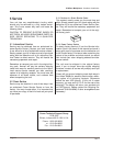
3.3.1 Mic/Line Inputs
Three-terminal removable barrier block connectors
are provided for the audio inputs. Each input has an
input selector switch. Slide it to the left (M) for
microphone signal levels up to +7 dBu (0 dBu =