


Page 17
IQ Mixer/Multiplexer Hardware Installation
Rev. 0
system). Because the bus outputs are controlled by
the
IQ System
, they can be kept off until they are
actually used, preventing too many of them being
on at the same time and loading down a common
audio bus network.
The versatile bus outputs can be used for any audio
system, small or large, where switchable outputs
are desired, such as switchable recording outputs.
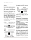
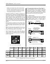
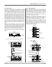
Both main and bus outputs are wired the same way.
Balanced output wiring is shown below.
Notice that the shield is not connected to the output
ground terminal if the load is connected to AC
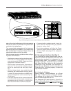
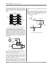
ground. This prevents unwanted ground loops. Un-
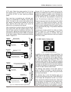
balanced output wiring is shown next.
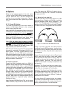
It is also possible to connect more than one ambient
sensing microphone to the sense input. This can be
accomplished by taking advantage of the manual
mixing function of Channel 2. Simply connect each
ambient sensing microphone to one of the five regu-
lar inputs of the
AMB-5
and use the IQ software to
assign each of them to Channel 2 only. Switch the
sense input to the line-level position (L) and connect
the main audio output of Channel 2 to it. Use the IQ
software to control the level of the ambient sensing
microphones. The microphones which are located in
more critical areas can be set to a higher level so
they will trigger the level controller first.
Be sure the microphone has adequate sensitivity for
the spectral content of the ambient sound. For ex-
ample, a microphone with a bandwidth designed
solely for speech reinforcement may not have ad-
equate low-frequency sensitivity to pick up the low-
frequency noise of machinery in a factory.
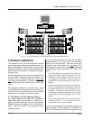
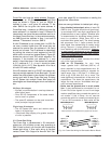
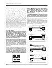
3.3.3 Audio Outputs
Three-terminal removable barrier block connectors
are provided for audio output (Figure 3.15). Both a
main and bus output are provided for each of the
two mixer channels. They are balanced and can
drive 1200 ohms or more to +26 dBu or 600 ohms to
+20 dBu. Each bus output can drive any number of
inputs within this impedance range.
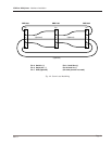
The main audio outputs are provided for connection
with other audio equipment such as power amplifi-
ers. They can also be stacked with the outputs of
other mixer/multiplexers to increase the number of
mixer inputs. For example, two 6x2
MPX-6s
can be
stacked to create a 12x2 mixer. This is described in
Section 3.3.4.
The bus outputs are turned on or off by relays and
function like the aux send outputs on a conventional
mixing console. They are switched on or off by the
IQ System
. This special design allows many bus
outputs to be connected to a common audio bus in a
multiple-zone network (like a large airport paging
Fig. 3.16 Balanced Audio Output Connections
Fig. 3.15 Audio Output Section
Fig. 3.17 Unbalanced Audio Output Connections
+–+–
AUDIO
OUT
1
MAIN BUS
STACK
IN
+–
OUTPUT
+
Output
Shield connected to ground
terminal of load only
Load
+–
OUTPUT
+
Output
Load
Twin-lead shielded cable
Single-conductor coax
or twisted pair
+–
OUTPUT
+
–
Output
Floating
load
2-wire line cord
(or battery power)
Shield not connected
at this end
+–
OUTPUT
+
–
Output
Grounded load
(power amp)
Shield connected at both ends
3-wire grounded line cord
(or other ground connection)