


4
Electrical Requirements
WARNING
To prevent an electric shock hazard, the power supply
must meet the specifications stated below. It is the own-
er’s responsibility to make sure that the electrical service
meets electrical requirements and that the electrical outlet
has been properly installed by a licensed electrician.
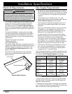
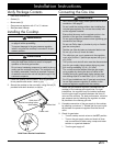
• The cooktop is supplied with a factory installed, 42-inch
long, power cord with a three-prong, grounding elec-
trical plug. It is connected to the chassis at the bot-
tom right rear corner (see Chassis Bottom Diagram
below). It must be connected to a dedicated, grounded
three-prong electrical outlet installed by a licensed elec-
trician.
• The electrical installation, including minimum supply
wire size and grounding, must be done in accordance
with National Electric Code ANSI/NFPA 70 and local
codes and ordinances. A copy of this standard may be
obtained from:
National Fire Protection Association
1 Batterymarch Park
Quincy, MA 02269-9101
• The correct voltage, frequency and amperage must be
supplied to the electrical outlet according to the product
data label located on the bottom of the chassis. See
the Gas and Electrical Requirements table on this
page for reference.
• Be certain to locate the electrical outlet so that the
power cord may be easily disconnected if the unit
requires service.
Gas Supply Requirements
• Be certain that the cooktop being installed is correct for
the gas service being provided (natural gas or LP gas).
Also, if operating the cooktop at an altitude above 4000
ft. (1219 m) make sure it is equipped for high altitude
operation.
• Units equipped for LP operation have “LP” in the
model number listed on the product data label. See the
Chassis Bottom Diagram for label location.
• Units equipped for high altitude operation have an “H”
at the end of the model number listed on the product
data label.
• Check your local building codes for the proper method
of installation. In the absence of local codes, this
appliance should be installed in accordance with the
National Fuel Gas Code ANSI Z223.1/NFPA 54.
• An external manual shut-off valve must be installed
between the gas inlet and the cooktop for the purpose
of turning on or shutting off gas to the appliance.
• The cooktop comes from the factory with a regulator in
the shipping carton. Use only the regulator provided.
The regulator must be installed in the gas line that runs
from the cooktop gas inlet to the gas shut off valve.
• The regulator inlet (female) accommodates a 3/4” gas
line. It can also accommodate a 1/2” gas line using
the included reducer. The inlet to the cooktop itself is
equipped with a ½” male NPT fitting.
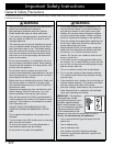
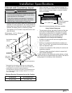
The cooktop gas connection is located on the bottom of the
cooktop in the back right corner as you face the front of the
unit. See the Chassis Bottom Diagram on this page.
DCT365S/NG DCT365S/LP
Gas type Natural gas LP gas
Manifold
pressure
5” Water
column
10” Water
column
Min. gas supply
pressure *
6” Water
column
11” Water
column
Max. gas supply
pressure
1/2 p.s.i. 1/2 p.s.i.
Total connected
load
0.25 Amp.
(30 Watts)
0.25 Amp.
(30 Watts)
Circuit
requirement
120 Vac,
60 Hz, 15 Amp.
120 Vac,
60 Hz, 15 Amp.
Gas and Electrical Requirements**
* The gas supply pressure for testing the regulator setting
shall be at least 1 inch water column (249 Pa) above the
specified manifold pressure.
** The electrical and gas data on this page is for reference
only. If the above data does not agree with the product data
label, use the data on the product data label.
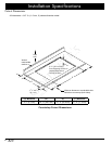
Front of unit
Product data label
Chassis Bottom Diagram
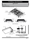
Installation Specifications