


7
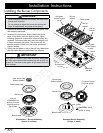
Verify Package Contents
• Hold down brackets (2)
• Grates (3)
• Burner sets (5)
• Gas pressure regulator with ¾” to ½” reducer
• Stainless steel cleaner
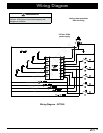
Installing the Cooktop
WARNING
• Verify that the power supply meets the specifications
on page 4 before proceeding.
• To prevent damage to the gas pressure regulator,
install it only after the cooktop is mounted in its per-
manent position.
CAUTION
• Do not over-tighten the hold down bolts. Over tight-
ening the hold down bolts may result in improper
operation of the dual gas burners.
• Do not use a hardening compound or caulk to perma-
nently seal the cooktop into place. The cooktop must
be readily removable if service is required. Removal
of sealant to service the unit will be performed at the
customer’s expense.
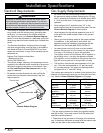
1. Lower the cooktop into the cutout. Slide it forward as
far as possible and center it side to side.
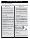
2. Secure the cooktop to the countertop using the two (2)
provided hold-down brackets as shown.
Installation Instructions
Connecting the Gas Line
WARNING
• Verify that the gas supply meets specifications before
connection. See page 4.
• Do not install the cooktop without also installing the
included gas regulator. Do not use the cooktop with-
out the regulator installed.
• Ensure that the arrow on the regulator points in the
direction of the gas flow, towards the cooktop.
• Do not apply excessive pressure when tightening gas
connections and fittings.
• Do not use Teflon tape or plumber’s putty on flexible
gas line connections.
• Test the gas lines for leaks as instructed before use.
Do not use a flame to check for leaks.
• The maximum gas supply pressure to the regulator
must never exceed ½ pounds per square inch (p.s.i.)
or 3.5 kPa.
• The cooktop and shut-off valve must be disconnected
from the gas supply piping system during any pres-
sure testing exceeding ½ p.s.i. (3.5 kPa).
• The cooktop must be isolated from the gas supply
piping system by closing the shut-off valve to the
cooktop during any gas supply piping system pres-
sure testing equal to or less than ½ p.s.i. (3.5 kPa).
• For LP gas installations, the LP gas tank must have
its own high-pressure regulator in addition to the
pressure regulator supplied with the cooktop.
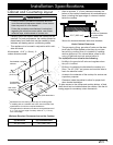
1. Attach the gas pressure regulator (included with the
cooktop) to the cooktop pipe nipple inlet. For tight
installations, the regulator may be installed upstream
from the pipe nipple, anywhere between the shut-off
valve and the cooktop. For best performance, minimize
gas pressure loss by attaching the regulator as close
as possible to the cooktop gas inlet.
2. Complete connection of the gas supply to the cooktop
by installing a minimum ½” flexible gas line (not includ-
ed) between the pressure regulator and the shut-off
valve.
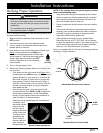
3. Check for gas leaks:
◊ Turn all cooktop control valves to the OFF position.
◊ Turn on the gas supply valve and check all lines
and connections for leaks using a soap and water
solution or a gas leak detector.
◊ Turn the gas supply off.
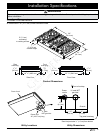
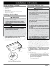
Hold Down Bracket Installation
Power cord
Gas inlet
Hold down
bracket mounting holes
(both sides)