


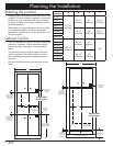
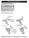
6
“C”
9 5/8” (244mm)
Recommended
(May be altered)
1 ¾“ (45mm)
Clear to Top
of Drawer for
Heat Exhaust
“B”
“A”
4“ Typical Toe Kick (Shown)
Recommended
Electrical
Location
3/4” (19mm)
Support Platform
1“ (25mm)
Clear to Top
of Drawer for
Heat Exhaust
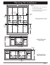
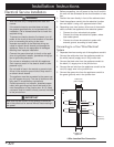
“C”
“A”
“B”
31 1/4” (794mm)
Recommended
(May be Altered)
1 ¾“ (45mm) Min.
Clear to Top of
Door for Heat
Exhaust
4“ Typical Toe Kick (Shown)
Recommended
Electrical
Location
Alternate
Electrical
Location
3/4” (19mm)
Support Platform
1“ (25mm) Min.
Clear to Top of
Door for Heat
Exhaust
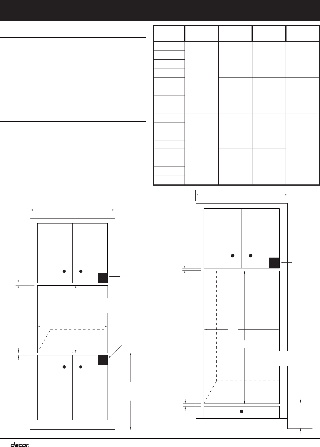
Planning the Installation
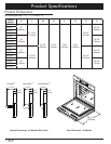
Model
Number
A B C D
EO127
27 7/16”
(697mm)
25 1/2”
(648mm)
27”
(686mm)
56 1/2”
(1435mm)
PO127
MOV127
MOH127
EO130
28 1/2”
(724mm)
30”
(762mm)
62 1/2”
(1588mm)
PO130
MOV130
MOV130
EO227
50 9/16”
(1284mm)
25 1/2”
(648mm)
27”
(686mm)
NA
PO227
MOV227
MOH227
EO230
28 1/2”
(724mm)
30”
(762mm)
PO230
MOV230
MOH230
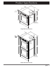
Single Wall
Oven Cutout
Double Wall
Oven Cutout
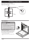
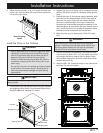
Selecting the Location
Carefully check the location where the oven is to be •
installed. The oven should be placed for convenient
access, but away from drafts that may be caused
by doors, windows, and heating, ventilation and air
conditioning outlets.
Make certain that electrical power can be provided •
in the selected location. Be certain that proper
clearance is provided for the oven door when it is in
the open position.
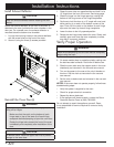
Cabinet Cut-Out
Plan the installation so that all minimum clearances •
are met or exceeded. Cutout dimensions shown
provide minimum clearances, unless otherwise
noted.
The specified minimum cabinet depth and width •
must be provided. The cabinet depth and width
must completely enclose the recessed portion of
the oven.
Cabinet cutout dimensions must be used as indi-•
cated.