


2
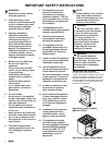
Verifying the Package Contents
If any item is missing or damaged, please
contact your dealer immediately. Do not install a
damaged or incomplete appliance.
All Ranges
• Use & Care Manual
• Anti-tip Bracket
• Broiler Grill and Pan
• Oven Racks
Ranges w/ Gas Top Burners & MRES30 Only
• Ignitor Cleaning Kit
• Burner Ring Set
• Grate/Burner Cap Pack
• Simmer Plate
Electric Ranges Only
• Razor Blade Scraper
• Cooktop Cleaning Cream
Gas Supply Requirements
Check your local building codes for the proper
method of installation. In the absence of local
codes, this appliance should be installed in
accordance with the National Fuel Gas Code
ANSI Z223.1. Be certain that the appliance
being installed is correct for the gas service
being provided.
WARNING:
This appliance must be installed
by a licensed plumber or gas
fitter when installed within the
Commonwealth of Massachusetts.
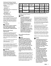
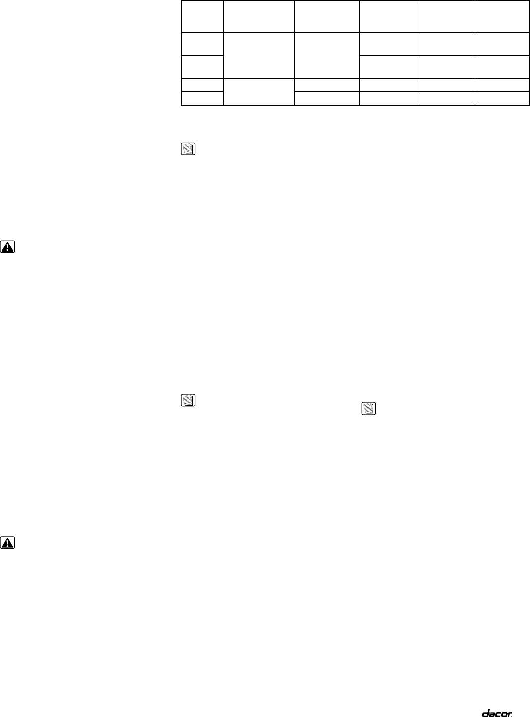
Dacor
Model
Number
Dedicated
electrical
circuit required
Total
connected
load Gas type
Manifold
pressure
Min. gas
supply
pressure
RSD30
120/240VAC,
60Hz, 30A
5.4kW (23.3A)
Natural
4” water
column
5” water
column
RSD30LP
Liquid Propane
10” water
column
11” water
column
RSE30
120/240VAC,
4-wire, 60Hz, 50A
11.1kW (46.7A) N/A N/A N/A
MRES30 10.3kW (43.7A) N/A N/A N/A
Gas and Electrical Requirements
Electrical Power Supply
Requirements
It is the owner’s responsibility to ensure that
the electrical connection of this appliance
is performed by a qualified electrician. The
electrical installation, including minimum supply
wire size and grounding, must be in accordance
with the National Electric Code ANSI/NFPA 70-
2002* (or latest revision) and local codes and
ordinances.
*A copy of this standard may be obtained from:
National Fire Protection Association
1 Batterymarch Park
Quincy, Massachusetts 02269-9101
The correct voltage, frequency, and amperage
must be supplied to the appliance from a
separate, grounded, circuit that is protected by a
properly sized circuit breaker or time delay fuse.
Refer to the data plate, and/or the Table above,
for gas supply requirements.
WARNING:
If the gas or electric service
provided does not meet the
product specifications, do not
proceed with the installation.
Call the selling dealer, the gas
supplier, or a licensed electrician.
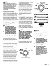
NOTES:
1. The power supply must
be properly polarized.
Reverse polarity will result in
continuous sparking of the
electrodes, even after flame
ignition.
2. If there is any doubt as to
whether the power supply
is properly polarized or
grounded, have it checked by
a qualified electrician.
3. If the appliance is connected
to a 120/208 volt power supply,
preheat times and cavity
temperature recovery times
will be increased slightly.
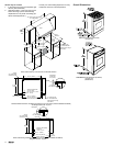
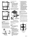
Gas and Electrical Rough-In
Locations
NOTE:
The shaded areas shown in
the illustrations, denotes the
location of the gas stub and the
electrical junction box/receptacle.
These are suggested locations.
For replacement purposes, the
location of the existing utilities
may be utilized provided that they
do not interfere with the sides
or rear of the range. Verify that
local building codes will permit
installing the gas valve behind the
range.
A manual shut off valve must be installed in the
gas piping, external to the appliance, for the
purpose of turning on or shutting off gas to the
appliance. Plan the location of the range and the
gas supply to allow access to the valve when
the unit is installed and in operation. Access to
the remote circuit breaker panel/fuse box, with
the range in place and operating, must also be
allowed for in the installation. Any openings in
the wall behind the appliance and in the floor
under the appliance must be sealed.
Both the gas supply piping and shut-off valve,
and the electrical junction box/receptacle must
be located so they do not interfere with the
range when it is installed and under operation.
In addition, the junction box must be located
so the range can be removed for service when
the conduit supplied with the unit is attached to
the junction box. Do not lengthen the conduit or
wiring provided with the range.
All dimensions shown are based on standard
American cabinets 36 inches (914mm) high
at the finished countertop by 24 inches
(610mm) deep, with a 25 inch (635mm) overall
countertop depth. When installing the range
into nonstandard cabinets, minimum clearances
shown in the diagrams must be maintained.
Carefully check the location where the range is
to be installed. For best performance, the range
should be placed away from drafts that may be
caused by doors, windows and HVAC outlets.
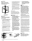
Cabinet and Countertop Preparation
NOTES:
1. If cabinet storage space is to
be provided directly above
the range, the risk of personal
injury may be reduced by
installing a ventilating hood
that projects horizontally a
minimum of 5 inches (127mm)
beyond the face of the
cabinets.
2. The range may be installed
flush to the rear wall. We
recommend installing a non-
combustible material on the
rear wall above the range
and up to the vent hood. It
is not necessary to install
non-combustible materials
behind the range below the
countertop height.
3. The minimum distance from
the sides of the range above
the countertop to combustible
side walls must be at least 6
inches (152mm).
The above electrical specifications are for reference only. See the range data plate for exact
specifications. See page 1 for location.