


4
4. Do not install a fuse in the
neutral or ground circuit. A
fuse in the neutral or ground
circuit may result in an
electrical shock hazard.
5. Do not ground the appliance
to a gas supply pipe or hot
water pipe.
6. A grounded cold water pipe
must have metal continuity to
electrical ground and must not
be interrupted by insulating
materials. Any insulating
materials must be jumped
with a length of No. 4 copper
wire securely clamped to bare
metal at both ends.
Grounding Instructions (All Models)
This appliance must be electrically
grounded.
With the range positioned directly in front of
the cabinet cutout, feed the appliance conduit
to the electrical junction box. Then, depending
upon local codes, utilize one of the following
techniques to connect the appliance to the
electrical power supply:
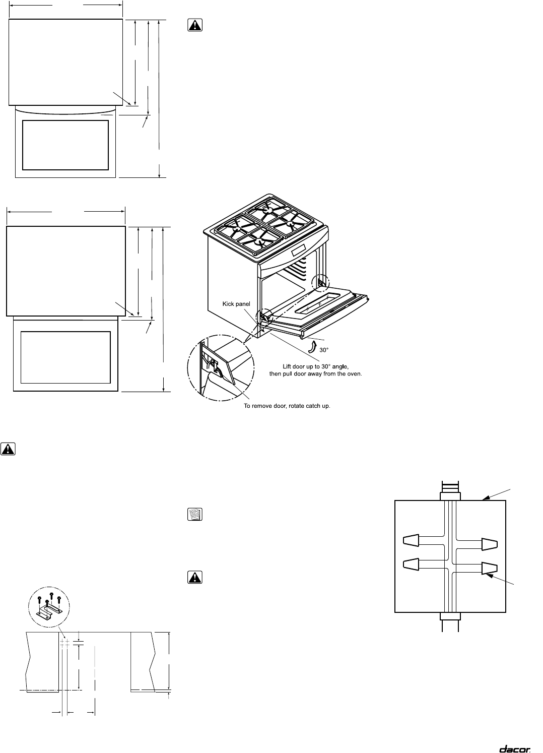
A. Connecting to a Four-Wire Electrical
System. (Recommended for All Models)
1. Separate the green and white appliance
wires.
2. Connect the white appliance wire to the
neutral (white) supply wire in the junction
box.
3. Connect the black appliance wire to the
black (L1) power supply wire in the junction
box.
4. Connect the red appliance wire to the red
(L2) power supply wire in the junction box.
5. Connect the green appliance wire to the
green house grounding wire in the junction
box.
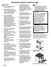
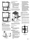
Door Opened
Range Top
23 1/2"
(597mm)
26 9/16"
(675mm)
Rear of Control
Panel/Oven Door
Max. depth
to oven door
handle with
door closed
30"
(762mm)
45 1/4"
(1149mm)
Overall Dimensions (Preference Models)
Isometric View
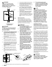
Door Opened
Range Top
23 1/2"
(597mm)
25 5/16"
(643mm)
Rear of Control
Panel/Oven Door
Max. depth
to oven door
handle with
door closed
30"
(762mm)
45 1/4"
(1149mm)
Overall Dimensions (MRES Model)
Isometric View
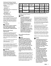
Installing the Anti-Tip Bracket
WARNING:
This appliance require an anti-
tip device. Before installing the
range, you must locate and secure
the anti-tip bracket to the floor.
When the range is slid into position in the
cutout, the left rear leveling leg slides into this
bracket to prevent the unit from tipping forward.
The bracket location shown here will position the
rear edge of the range top frame flush to the rear
wall. From this position, the bracket allows for up
to 5/8” (16mm) of forward movement of the range.
1 1/2”
(38mm)
24”
(610mm)
1”
(25mm)
11
3/8”
(289mm)
2 3/16”
(556mm)
Front face
of cabinet
19 7/16”
(494mm)
C
L
Location of Anti-Tip Bracket
Top View
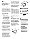
Removing the Oven Door
WARNINGS:
1. Do not attempt to disengage
the hinge catches with the
door removed from the oven.
The hinge springs could
release causing personal
injury.
2. Do not lift or carry the oven
door by the door handle.
Open the door to its fully opened position.
Rotate the catch over the retaining arm on each
hinge. Lift the oven door to about a 30 degree
angle from the horizontal position. Pull the door
away from the oven while continuing to lift.
Removing the Oven Door
Remove the Kick Panel (All Models)
Remove the screw at each top corner of the
kick panel. Lift up slightly on the panel and pull
forward to remove
Electrical Connection
NOTE:
See the range data plate for
electrical specifications. See
page 1 for location.
WARNINGS:
1. All of these range models
must be connected to a
grounded, metallic, permanent
wiring system. Alternatively, a
grounding conductor should
be connected to the grounding
terminal or lead on the
appliance.
3. Do not use an extension cord
with this appliance. Such use
may result in fire, electrical
shock, or other personal
injury.
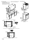
Conduit from
appliance
Cable from
power supply
Wire nut
(4 places)
Junction
box
RED
RED
GREEN
GREEN
WHITE
WHITE
BLACK
BLACK
Connecting the appliance to a
four-wire power supply
(All Models)