


5
5. The maximum gas supply
pressure to the appliance gas
pressure regulator must never
exceed 1/2 pound per square
inch (3.5kPa).
NOTE:
The applaince gas pressure
regulator is pre-set at the factory
for the type of gas intended for
use with the appliance. Verify
that the appliance is compatible
with the type of gas available by
checking the data plate located
behind the inlet air cooling grill.
Ranges intended for use with LP
gases will have “LP” as a part
of the model number. Consult
your dealer if the range is not
compatible with your gas supply.
WARNING:
**Do not connect the green
appliance wire to the neutral
(white) supply wire unless local
building codes permit.
WARNING:
The RSD30 cannot be connected
as above because it will damage
the spark module.
B. Connecting the Green Appliance Wire to
the Neutral (White) Supply Wire – Where
Local Codes Permit. (RSE/MRES30
Only)
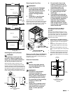
1. Connect the green and white appliance
wires to the neutral (white) supply wire in
the junction box.
2. Connect the black appliance wire to the
black (L1) power supply wire in the junction
box.
3. Connect the red appliance wire to the red
(L2) power supply wire in the junction box.
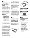
C. Connecting the Green Appliance Wire to
a Grounded Supply Wire or a Grounded
Cold Water Pipe – Where Local Codes
Permit. (All Models)
1. Separate the green and white appliance
wires.
2. Connect the white appliance wire to the
neutral (white) supply wire in the junction
box.
3. Connect the black appliance wire to the
black (L1) power supply wire in the junction
box.
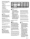
Conduit from
appliance
Cable from
power supply
Wire nut
(3 places)
Junction
box
RED
RED
GREEN
WHITE
WHITE
BLACK
BLACK
**Connecting the appliance to a
three-wire power supply
(RSE/MRES30 Only)
Conduit from
appliance
Cable from
power supply
Wire nut
(4 places)
Junction
box
RED
RED
GREEN
GREEN
WHITE
WHITE
BLACK
BLACK
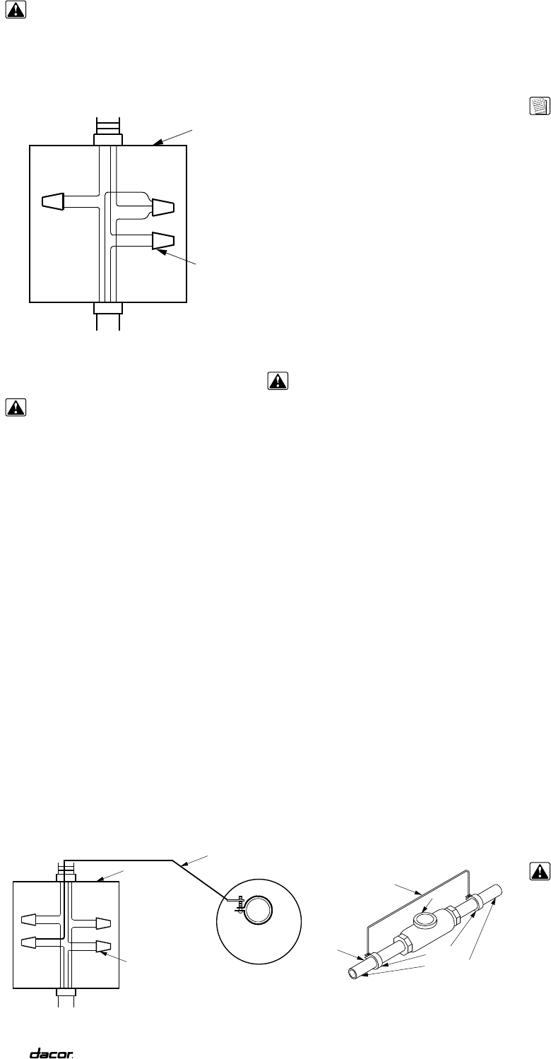
Separate No. 10 (minimum)
copper grounding wire
Clamp must be
tight on pipe
No. 4
copper wire
Metal
water pipe
Clamps
Bare metal
Meter
Connecting the appliance ground to a grounded junction box wire or grounded cold water pipe
Gas Connection
Before sliding the range into the cabinet,
connect a flexible gas connector to the gas
shut-off valve previously installed on the stub
out. The gas valve must be turned off during
installation. Connect the flex connector to the
pipe fitting at the right rear of the range.
WARNINGS:
1. Do not apply excessive
pressure when tightening gas
connections and fittings.
2. Do not use teflon tape or
plumber’s putty on gas flex
line connections.
3. Turn all cooktop control valves
to the “OFF” position. Turn
on gas supply and check all
lines and connections for
gas leaks using a soap and
water solution. Do not use a
flame to check for leaks. After
verifying that there are no gas
leaks, turn off the gas supply
to the range by turning the gas
shut-off valve to the “OFF”
position.
4. For LP installations, the LP
gas tank must have its own
high pressure regulator. This
is in addition to the pressure
regulator provided with the
range.
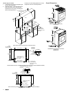
Installing the Range
Measure from the floor to the countertop and
adjust the leveling legs as required to position
the top frame at the desired height, based on
the cabinet and countertop installation. Carefully
slide the range into position in the cutout. (The
left rear leveling leg should engage the anti-tip
bracket.)
When the range is to be installed as a “slide-in,
self rimming” (with the range top overhanging
the countertop cutout), measure from the floor
to the countertop. Adjust the leveling legs to
position the bottom edge of the range top frame
approximately 1/8” (13mm) above the level of
the countertop. This will allow the range to slide
over the countertop. Carefully slide the range
into position in the cutout. Again, the left rear
leveling leg should engage the anti-tip bracket.
To lower the range onto the countertop, turn the
leveling legs counterclockwise. Lower the range
until the bottom of the range top just contacts
the countertop. Do not allow the full weight of
the range to hang on the counter.
Installing the Burner Components
Remove the brass burner rings, porcelain burner
caps, and porcelain gates from their shipping
packages. Place each burner ring onto its
corresponding burner base, being certain that
the five alignment tabs slide into the matching
notches in the base. Set each porcelain burner
cap on top of its corresponding burner ring.
Place each grate onto the top frame, being
certain that the rubber feet are positioned in the
locating dimples.
WARNING:
Never attempt to operate the
cooktop section of the range with
any of the burner rings, burner
caps or grates removed.
4. Connect the red appliance wire to the red
(L2) power supply wire in the junction box.
5. Connect the green appliance wire to a
grounded supply wire in the junction box or
to a grounded cold water pipe.
6. If connecting to a grounded cold water
pipe, a separate copper grounding wire
(No. 10 minimum) must be connected to a
grounded cold water pipe by means of a
clamp and then to an external grounding
connector screw.
6. A grounded cold water pipe must have
metal continuity to electrical ground and
must not be interrupted by insulating
materials. Any insulating materials must be
jumped with a length of No. 4 copper wire
securely clamped to bare metal at both
ends.