


Installer F inal Checklist
16
GENERAL
❏ Placement of Unit.
❏ Specified clearance maintained to cabinet
surfaces.
❏ Unit Level- front to back, side to side.
❏ All packaging material and tie straps removed.
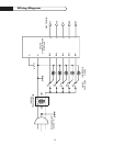
ELECTRICAL:
❏ Receptacle with 15 ampere current
protection is provided for service cord
connection.
❏ Adequate ground connection.
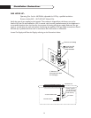
GAS SUPPLY:
❏ Connection: 1/2 NPT with a minimum 5/8”
diameter flex line
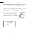
❏ The pressure regulator which is connected to
the manifold is set for 4.0”-for Natural Gas
❏ Manual gas shut off valve installed in an
accessible location.
❏ Unit tested and free of gas leaks
OPERATION:
❏ All internal packing materials are removed, i.e.
below grates, around knobs, etc.
❏ Bezels centered on burner knobs and knobs
turn freely.
❏ Each burner lights satisfactorily, both
individually and with other burners operating.
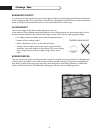
❏ Flame adjustment for 3/8" soft blue cone
made on ports of each top burner.
❏ Low flame operation verified.
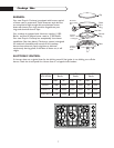
❏ All burner caps, burner rings and burner
bases correctly seated in position, level, and
do not rock or slide.
❏ Burner grates correctly positioned, level, and
do not rock.