


20
ባ
OPERATIONS TO BE PER-
FORMED WHEN SUBSTI-
TUTING THE INJECTORS
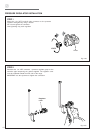
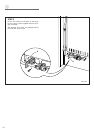
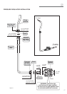
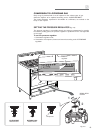
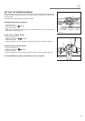
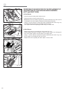
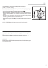
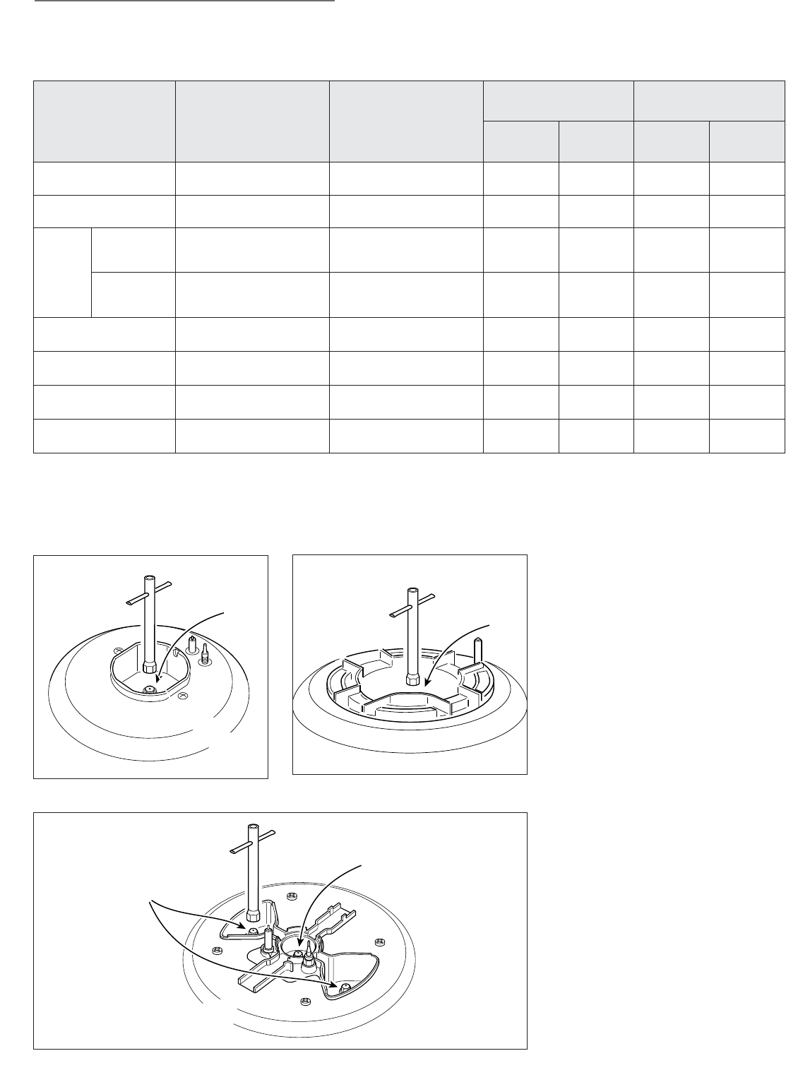
✓ Remove the gratings and the burner
covers;
✓ Using a wrench substitute the nozzle
injectors “J” (figs. 2.6a - 2.6b - 2.6c)
with those most suitable for the kind of
gas for which it is to be used.
The burner are conceived in such a
way so as not to require the regulation
of the primary air.
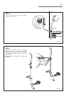
Fig. 2.6a
Fig. 2.6b
Fig. 2.6c
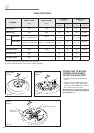
INJECTORS TABLE
Semi-rapid
burner
Triple ring
burner
DUAL
burner
BURNERS
NOMINAL POWER
BTU/hr
REDUCED POWER
BTU/hr
LP/PROPANE
11” W.C.P.
NATURAL GAS
4” W.C.P.
Ø injector
[1/100 mm]
By-pass
[1/100 mm]
Ø injector
[1/100 mm]
By-pass
[1/100 mm]
Semi-rapid (R)
6000 1500 72 32 118
adjustable
Triple ring (TC)
12000 5000 102 65 170
adjustable
Oven burner (left)
13000 1500 109 34 180
adjustable
Oven burner (right)
9000 1400 88 33 145
adjustable
Broil burner (left)
8500 - 88 - 146 -
Broil burner (right)
8000 - 83 - 140 -
Dual (D)
Inner crown
2800 for NATURAL GAS (*)
3500 for LP/PROPANE GAS (*)
1000 (*)
55
(no. 1 central)
27
80
(no. 1 central)
adjustable
Outer crowns
16000 for NATURAL GAS (#)
15000 for LP/PROPANE GAS (#)
6500 for NATURAL GAS (#)
4500 for LP/PROPANE GAS (#)
72
(no. 2 outer)
60
130
(no. 2 outer)
adjustable
J
Injector for inner crown
J
Injectors for
outer crowns
J
J
(*) Power calculated only with inner crown operating
(#) Power calculated with inner and outer crowns operating