


25
ቤ
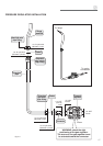
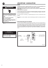
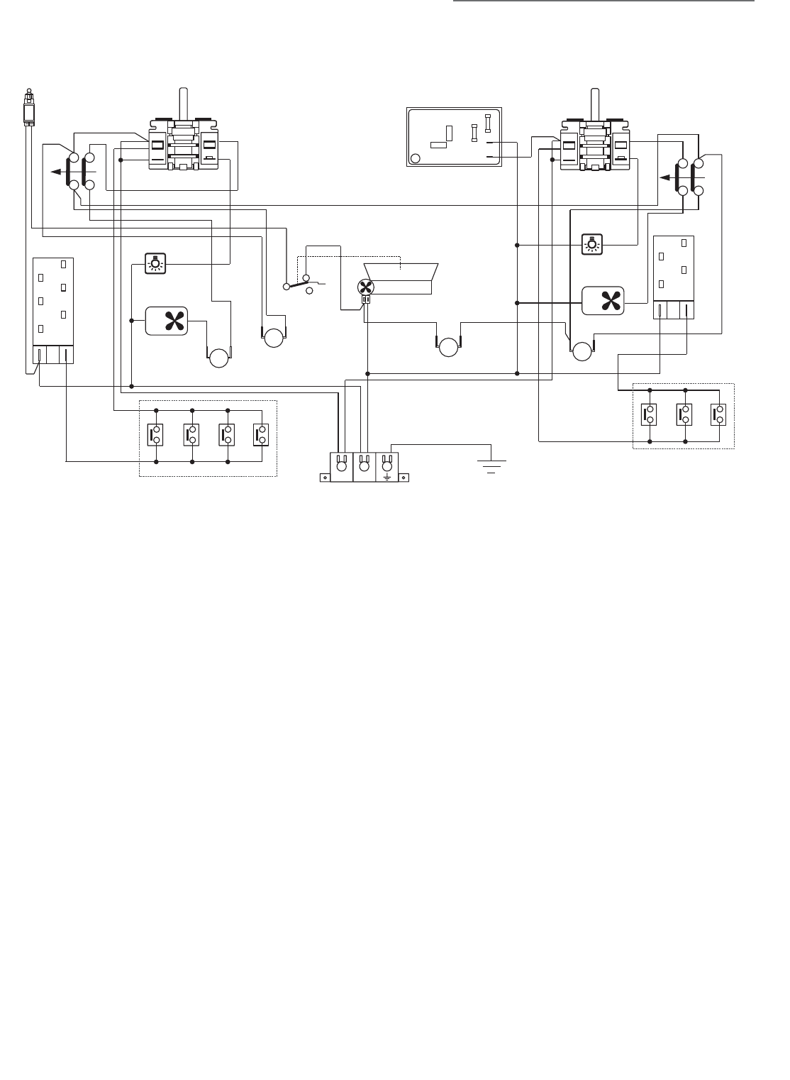
WIRING DIAGRAM
ELECTRIC DIAGRAM KEY
RIGHT OVEN
F1 Switch
MS Security switch
S1 Cooling fan failure lamp
LFOven lamp
ASAir switch
V Fan motor
TL1/2 Thermal overload
PAIgnition switches group
AIgnition coil
LEFT OVEN
F2 Switch
MS1Security switch
LF1Oven lamp
ECElectronic clock
V1 Fan motor
PA1Ignition switches group
A1Ignition coil
TL4 Thermal overload
CF Cooling fan motor
TL3 Thermal overload
M Terminal block
T Earth connection
N/7
L/8
LF
AS
M
N
L
CF
V
LF1
V1
TL1
TL2
TL3
TL4
F1
S1
MS
EC
F2
MS1
A1
A
PA
PA1
T
1
2
P2
P1
1
2
P2
P1