


17
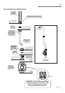
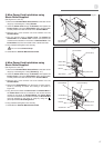
4-Wire Power Cord Installation using
Strain Relief Supplied
(See Figures 3.1 and 3.3)
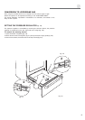
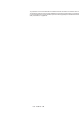
1. Remove the Terminal Block Access Plate on the back of the
range by unscrewing the 4 fixing Screws (fig. 3.1).
2. Insert the Power Cord through the Bracket; then tighten the
Power Cord by using the Strain Relief. Allow enough slack
to easily attach the cord terminals to the Terminal Block.
3. Remove the 3 wire terminal nuts and washers from the
Terminal Block.
4. Remove the Ground Strap from the frame of range and ter-
minal by removing its screw and cutting it as shown in
Figure 3.3.
5. Plug the terminal holes of Power Cord. The Neutral Wire of
the Power Cord must be connected to the neutral terminal
located in the center of Terminal Block; the Power Wires
must be connected to the outside terminals; the Ground Wire
must be attached to the frame of range by using the
(Ground) identified Grounding Screw.
6. Plug washers and tighten nuts securely.
7. Assemble the Terminal Block Access Plate.
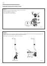
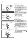
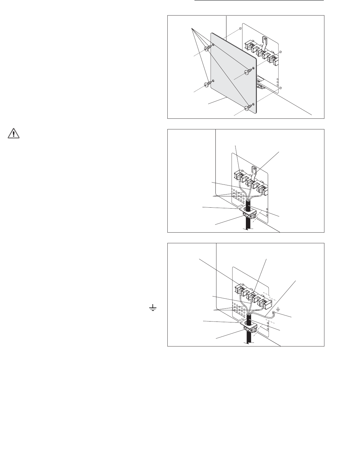
3-Wire Power Cord Installation using
Strain Relief Supplied
(See Figures 3.1 and 3.2)
1. Remove the Terminal Block Access Plate on the back of the
range by unscrewing the 4 fixing Screws.
2. Insert the Power Cord through the Bracket; then tighten the
Power Cord by using the Strain Relief. Allow enough slack
to easily attach the cord terminals to the Terminal Block.
3. Remove the 3 wire terminal nuts and washers from the
Terminal Block.
4. Plug the terminal holes of Power Cord. The Neutral or
Ground Wire of the Power Cord must be connected to the
neutral terminal located in the center of Terminal Block. The
Power Wires must be connected to the outside terminals.
5. Plug washers and tighten nuts securely.
Do not remove Ground strap.
6. Assemble the Terminal Block Access Plate.
Terminal Block
Access Plate
Screws
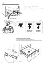
Neutral Wire
Power Wires
Bracket
Power Cord
Terminal Block
Ground strap
Strain Relief
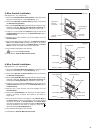
Neutral Wire
Power Wires
Bracket
Power Cord
Terminal Block
Grounding Wire
Strain Relief
Cut Ground Strap
Grounding Screw
Fig. 3.1
Fig. 3.2
Fig. 3.3
ቤ