


14
Fig. 3.1a
Fig. 3.1cFig. 3.1b
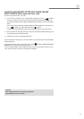
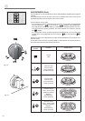
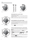
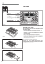
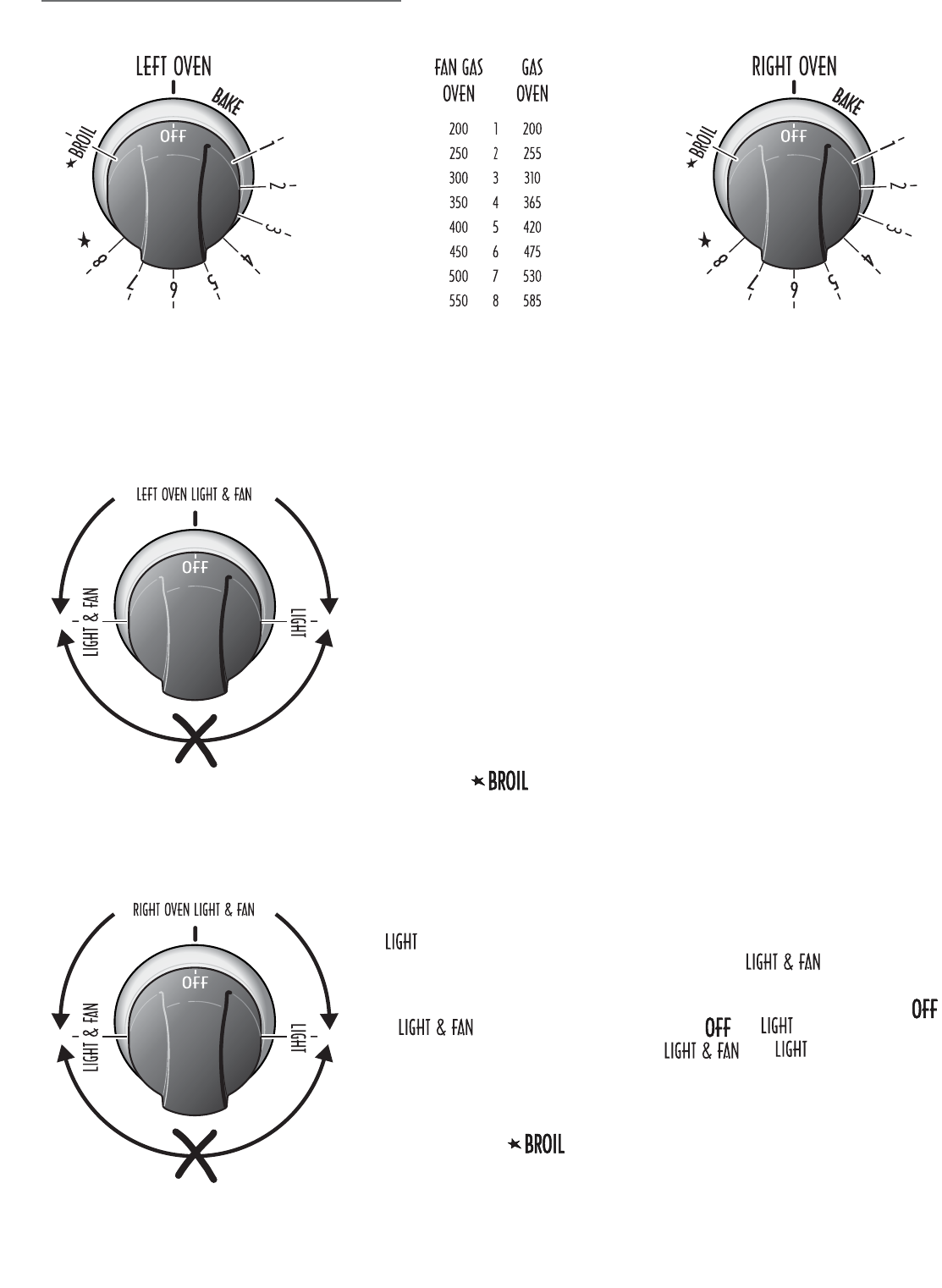
OVEN THERMOSTAT (LEFT and RIGHT OVEN)
The numbers printed on the control knob (fig. 3.1a - 3.1c) indicate the increasing
oven temperature value (see temperature table near the control knob - fig. 3.1b).
Left column of the temperature table refers to oven burner used in combination
with the fan motor while right column refers to oven burner used in the normal con-
vection mode (without fan motor).
To regulate the temperature, set the chosen number onto the control panel indica-
tor.
The position serves only to turn on the broil burner.
ቤ
OK OK
NOT TURN
Fig. 3.2a
OK OK
NOT TURN
Fig. 3.2b
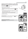
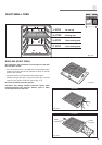
OVEN BURNER (LEFT and RIGHT OVEN)
It carries out normal “oven cooking”.
The gas flow to the burner is regulated by a thermostat which allow to maintain the
oven temperature constant.
The control of the temperature is assured by a thermostatic probe positioned inside
the oven.
The probe must be always kept in its housing, in a clean condition, as an incorrect
position or encrustment may cause an alteration in the control of the temperature.
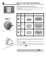
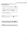
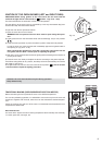
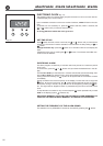
OVEN LIGHT AND FAN MOTOR (LEFT and RIGHT OVEN)
The oven light and the fan motor are controlled by a switch knob on the control
panel (fig. 3.2a - 3.2b). To light up the oven lamp turn the knob anti-clockwise to
position.
To operate the fan motor turn the knob clockwise to position.
In this setting also the oven lamp is lighted.
WARNING: The switch knob can be turned only clockwise from
to position and anti-clockwise from to position.
The switch knob DO NOT TURN from to position. DO NOT
FORCE.
IMPORTANT NOTE: The fan motor can be used in combination only with the oven
burner. A safety device switches off the fan motor when the gas oven/broil control
knob is turned on position.
IMPORTANT NOTE FOR THE SMALL RIGHT OVEN: The fan motor, when turned
on, starts to operate after about 3 minutes from the ignition of the oven burner.