


Page 3.
MODELS SIG80 / SIG80M / SIG110 / SIG110D / SIG110H
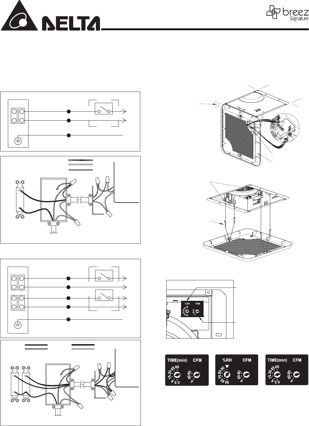
3. Connect wiring
3-1. Follow all local electrical and safety codes
3-2. NEVER place a switch where it can be reached from a tub
or shower
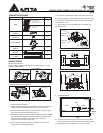
3-3. Connect wires as shown in wiring diagrams.
Single Speed Models: SIG80, SIG110
Motion Model: SIG80M
OFF
ON
L
N
POWER SWITCH
JUNCTION BOX
SWITCH BOX
WHITE
BLACK
GREEN
GRD
BLACK
ON/OFF SWITCH
(purchase separately)
SWITCH BOX
120 VAC
LINE IN
WHITE
GROUND
(bare)
POWER
SWITCH
WIRING
PLATE
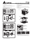
Humidity Model: SIG110H
Dual Speed Model: SIG110D
HI
POWER SWITCH
MODE SWITCH
JUNCTION BOX
SWITCH BOX
WHITE
BLACK
OFF
ON
WHITE
BLUE
GREEN
GRD
L
N
L
N
ON/OFF SWITCH
(purchase separately)
SWITCH BOX
120 VAC
LINE IN
WIRING
PLATE
BLACK
WHITE
GROUND
(bare)
BLUE
MODE
SWITCH
POWER
SWITCH
3-4. Using wire nuts (not provided), connect the house power
cable to the ventilating fan wires.
is the smallest conductor that shall be used
for branch-circuit wiring.
4. Grille attachment
4-1. Insert the motion sensor unit into the grille (Fig. G) (only for
SIG80M)
4-2. Insert the mounting springs into the slots and mount the grille
to the body. (Fig. H)
Celling
Sensor unit
Grille
Fig. G
Slots
Spring
Fig. H
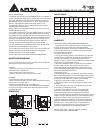
5. Operation
Delay time control
(SIG80M & SIG110D)
or Humidity preset control
(SIG110H).
SIG110H SIG110DSIG80M
Low speed air volume
preset control (SIG80M,
SIG110H, SIG110D).
control options
Single Models: SIG80, SIG110
5-1. Single speed control mode: Turn the POWER switch on to
operate at single speed mode
the LED indicator will be green.
3-5. 14 AWG (2.1 mm
2
)