


106828-01D
For more information, visit www.desatech.com
For more information, visit www.desatech.com
6
CAST IRON STOVE AND B-VENT
BURNER SYSTEM ASSEMBLY
Continued
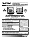
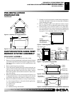
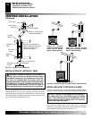
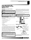
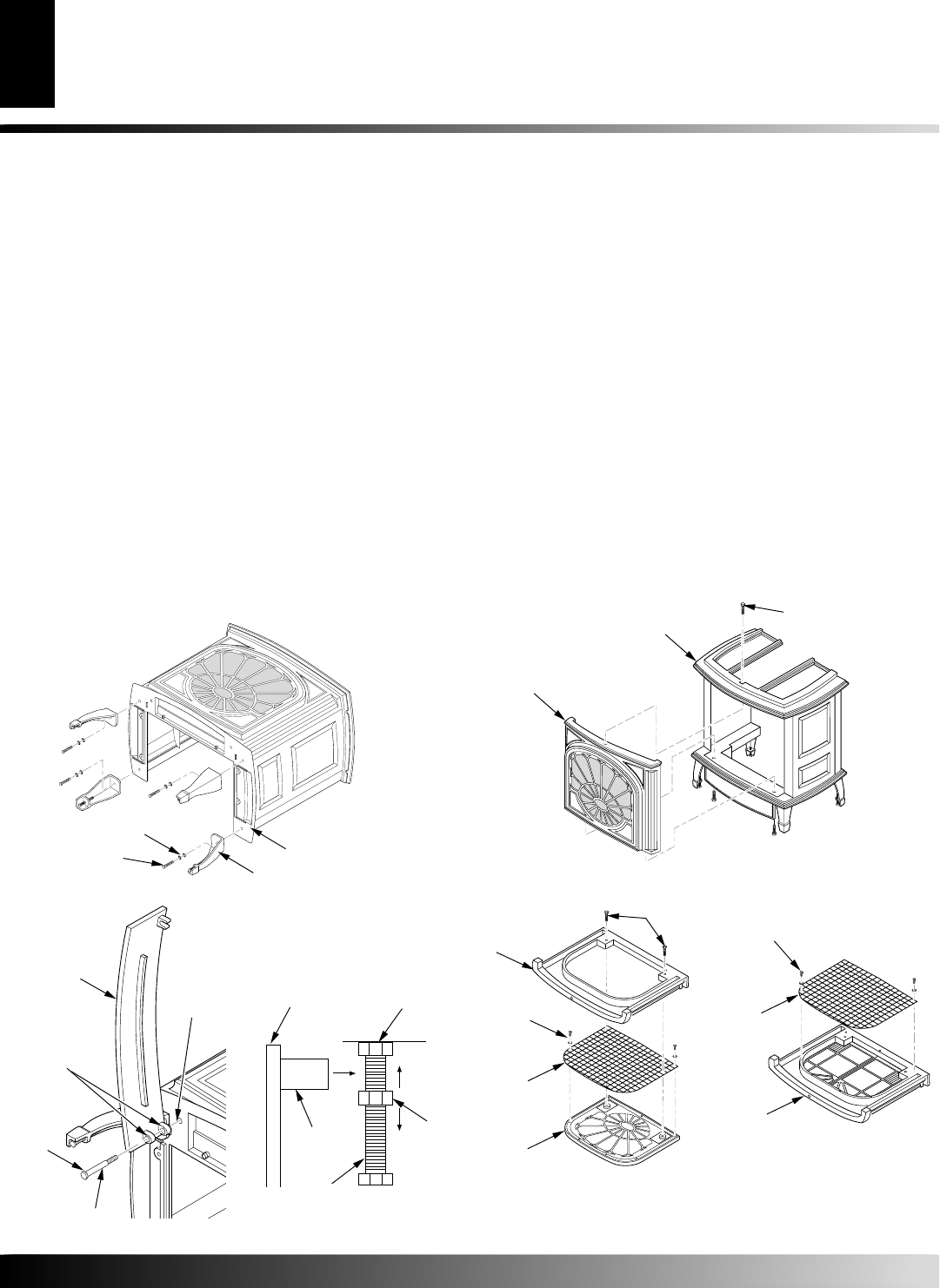
Figure 11 - Attaching Stove Door
Step
Bolt
Door Hinge
Threaded
Hole
Stove Door
Bolt Shoulder
Adjusting
Nut
Bolt Stop
Catch Bolt
Door Claw
Door
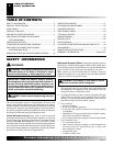
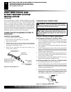
Figure 12 - Catch Bolt and
Door Claw Orientation
10. Attach stove door by inserting step bolt through door hinge
pivot hole and into threaded hole in stove body (see Figure 11
and Figure 9 on page 5). Use an adjustable wrench or a 12mm
socket to fasten step bolt. Tighten step bolt until snug. Make
sure door moves freely.
11. Install door catch bolt (M8 x 1.25-55mm with two M8 hex
nuts) into threaded hole on stove body (see Figure 9, page 5).
Use an adjustable wrench or a 12mm socket. The catch bolt
has two hex nuts attached to it (see Figure 12). The top nut is a
bolt stop and the bottom nut is for door leveling adjustment.
12. Check general catch bolt alignment with door claw. Make fi-
nal adjustment and door leveling after stove is in normal stand-
ing position.
13. Carefully lift stove back up on its four attached legs.
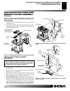
Removing Front Surround Panel
Remove 2 bolts from bottom of stove and set aside. Remove bolt
from the top of the stove to remove the front panel assembly (see
Figure 13).
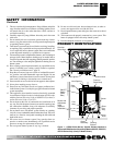
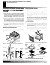
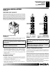
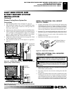
Figure 10 - Attaching Stove Legs (Amity™ Model Shown)
Bottom Of
Stove Unit
Leg
Bolt
Washers
Removing Screen (Optional)
Amity Models
1. Lay the front panel assembly face down on a protected sur-
face. Remove the two screws that hold the front plate onto the
front surround plate (see Figure 14). Save these screws.
2. Remove the screws and washers that hold the screen onto the
front surround plate. Discard these screws, washers, and screen
(see Figure 14).
3. Replace the two screws from step 14 to reassemble the front
plate and the front surround plate. Set this assembly aside un-
til burner system has been installed, logs have been placed
inside of burner system, and glass door to burner system insert
has been replaced.
Victor Hearth Models
1. Lay the front panel assembly face down on a protected sur-
face. Remove the screws and washers that hold the screen onto
the front surround plate. Discard these screws, washers, and
screen (see Figure 14).
2. Set this assembly aside until burner system has been installed,
logs have been placed inside of burner system, and glass door
to burner system insert has been replaced.
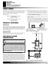
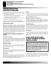
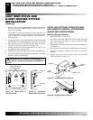
Figure 13 - Removing Front Assembly (Amity™ Model Shown)
Front
Assembly
Bolt
Stove Body
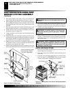
Figure 14 - Removing Screen from Front Assembly
Screws
Front
Surround
Plate
Front Plate
Screen
Screw with
Washer
CAST IRON STOVE AND B-VENT BURNER SYSTEM ASSEMBLY
Stove Body Assembly (Cont.)
Amity™ Model
Victor Hearth™ Model
Screw with
Washer
Screen
Front Surround
Plate and
Doors