


12
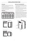
MAINTENANCE & SERVICE
REPLACING THE HEATER
The heat necessary for the operation of an absorption cooling
unit is supplied by an electric heater mounted in a pocket of
the boiler system.
The refrigerator is equipped with two electrical heaters, one
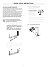
To replace the heater proceed as follows:
Unplug the refrigerator power cord from the 230-
Shut off gas valve.
Remove the terminal block cover.
With a pair of pliers unfold the lug holding the lid
of the boiler casing and open the lid.
Remove some insulation wool so that the heater is
accessible.
Turn and lift the heater out of its pocket.
Fit the new heater into the pocket.
Connect the leads and put on the terminal block
cover.
Put back the insulation and close the lid of the
boiler.
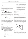
PERIODIC MAINTENANCE
Checking the connections
the refrigerator) for gas leaks. The LP gas supply must be
turned on. Apply a non-corrosive bubble solution to all LP
gas connections. The appearance of bubbles indicates a
leak and should be repaired immediately by a qualied
serviceman.
Checking the LP gas pressure
The LP gas pressure should be checked and the main regula-
tor readjusted if pressure is incorrect. The correct operating
pressure is 2,7 kPa. The correct place to measure the LP gas
pressure is at the test port just ahead of the burner jet.
1.
2.
3.
4.
5.
6.
7.
8.
9.
10.
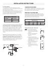
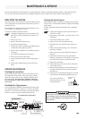
Cleaning the ue and burner
of soot. Heavy soot formation indicates improper functioning
of the burner.
manner:
Unplug the refrigerator power cord from the 230-
240 volt AC outlet.
refrigerator.
Turn manual shutoff valve to OFF.
Remove cover from the burner housing.
-
trode.
Remove the burner mounting screw and remove
the burner assembly.
-
Clean burner tube with a brush. Blow out burner
with compressed air.
Before removing burner jet, clean burner area of
the burner jet.
Soak the jet in wood alcohol and blow it out with
compressed air. Reinstall and tighten burner jet.
shall be clear blue over the
slots of the burner.
1.
2.
3.
4.
5.
6.
7.
8.
9.
10.
11.
12.
Do not use a wire or pin when cleaning the burner
jet as damage can occur to the precision opening.
This can cause damage to the refrigerator or create
a re hazard.
WARNING
!
Clear blue colour
of flame
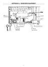
GAS EQUIPMENT ASSEMBLY
Shown in open position
Use a slotted screwdriver to change position
INLET FITTING
PRESSURE TEST PORT
BURNER JET
BURNER MOUNTING SCREW
BURNER TUBE
SPARK ELECTRODE
NUT
THERMOCOUPLE