


INSTALLATION
GENERAL INSTRUCTIONS
This appliance is designed for storage of foods and stor-
age of frozen foods and making ice.
The refrigerators outlined hereon have been design certified
under ANS
Z21.19a-
1984 Refrigerators by the American Gas
Association for installation in a mobile home or recreational
vehicle and are approved by the Canadian Gas Association.
The certifications are, however, contingent on the installation
being made in accordance with the following instructions as
applicable.
The installation must in the USA conform with:
1. National Fuel Gas Code ANSI
Z223.
l-l 984
2. Manufactured Home Construction and Safety Standard, Title
24 CFR, Part 32-80,
3. Recreational Vehicles ANSI/NFPA No. 501 C-1977
The unit must be electrically grounded in accordance with the
National Electric Code ANSI/NFPA No. 70-1984 when installed if
an external alternating current electrical source is utilized.
4. Any applicable local code
0
1.
Current CGA B 149 Gas Installation Codes
(3
b
a
d,&’
The installation must in Canada conform wi
2. Current CSA Standard Z 240.4 GAS
-
EQUIPPED
RECREATIONAL VEHICLES AND MOBIL HOUSING
3. Any applicable local code
The unit must be electrically grounded in
accordance
with
the
current CANADIAN ELECTRICAL CODE C 22 Parts 1 and 2.
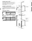
Ventilation
The installation shall be made in such a manner as to separate
the combustion system from the living space of the mobile home
or recreational vehicle. Openings for air supply or for venting of
combustion products shall have a minimum dimension of not
less than
1/4
inch.
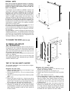
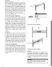
Proper Installation requires one lower fresh air intake and one
upper exhaust vent. The ventilation kits shown in this instruction
booklet have been certified for use with the
refrigerator
models
listed in the tables. Certified vent system kits, see separate
list. The ventilation kits must be installed and used without
modification. An opening towards the outside at floor level in the
refrigerator compartment must be provided for ventilation of
heavier-than-air fuel gases. The lower vent of the recommended
kits is provided with proper size openings. The flow of combus-
tion and ventilating air must not be obstructed.
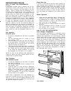
For ready serviceability of the burner and control manifold parts
of the refrigerator the lower side vent is fitted with a
liftout
panel
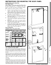
which provides an adequate access opening.
GAS CONNECTION
Hook-up to the gas supply line is accomplished at the manual
gas valve, which is furnished with a
3/8”
SAE (UNF
5/8-
18) male
flare connection. All completed connections should be checked
for leaks with soapy water.
The gas supply system must incorporate a pressure regulator to
maintain a supply pressure of not more than 11 inches water
gage.
When testing the gas supply system at test pressures in excess
of
1/2
psig the refrigerator and its individual shutoff valve must be
disconnected from the gas supply piping system.
When testing the gas supply system at pressures less or equal
1/2
psig the appliance must be isolated from the gas supply
piping
system by closing its individual manual shutoff valve.
in case detailed
Instructions
on the installation and connection to
the gas supply are required. contact your dealer or distributor.
ELECTRICAL CONNECTION
120
Volts A C
The refrigerator is equipped with a three prong (grounded) plug
for protection against shock hazards and should be plugged
directly into a properly grounded three prong receptacle. Do not
cut or remove the grounding prong from this plug. The cord
should be routed to avoid coming in contact with the burner cover
flue cover or other hot components.
Refrigerator models requiring 12 V DC
supply
On units provided with interior light or automatic reigniter or both
there is one additional terminal block marked “12
V”.
On “Three
Power” units with interior light or automatic reigniter or both there
are two additional blocks.
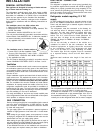
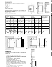
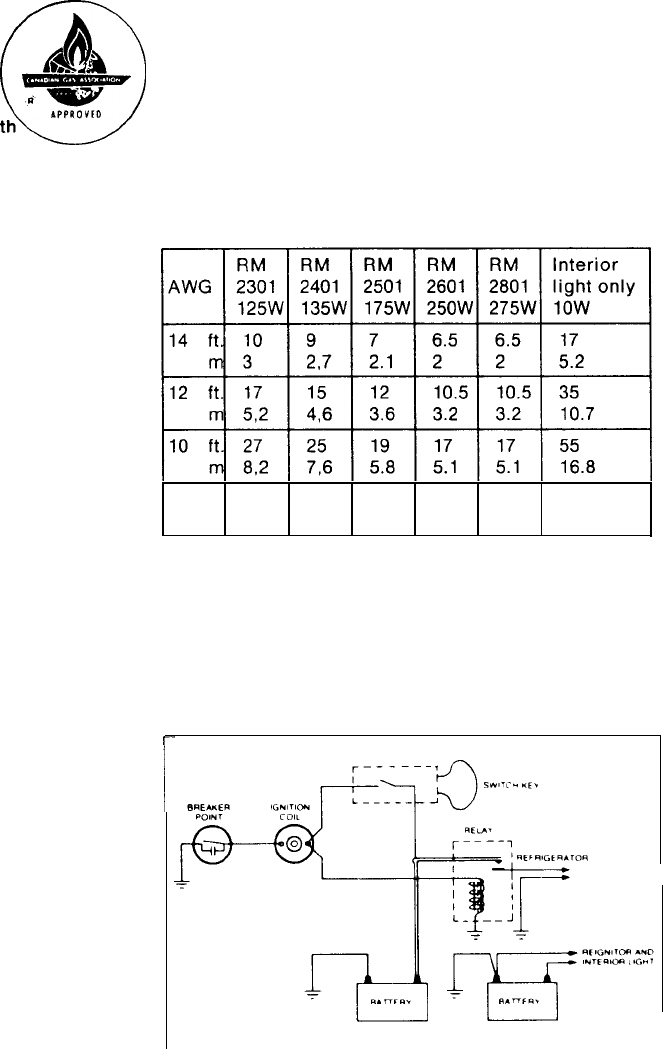
The refrigerator must be connected to the battery cir-
cuit with two wires of adequate capacity to avoid vol-
tage drop. The wire gage should be chosen with cons-
ideration to the wire length in accordance with table
below. The 12 V circuit must be fused. Maximum cir.-
cuit
fuse size: 15 Amps. for the models RM2301 and
RM2401, 20 Amps. for RM
2501, 25
Amps. for RM2601
and RM2801.
Do not use the body or chassis of the vehicle as a
substitute for either of the two conductors. No other
electrical eqiupment or lighting should be connected
to the refrigerator circuit. The refrigerator will draw
from 10 to 18 Amps at 12 Volt depending on model.
The interior light and the reigniter must be connected
to a separate battery circuit and will draw about 1
Amp.
Maximum total conductor wire length in feet and me-
ter.
8
ft. 43 40 31 27 27 85
m 13 12.2 9.5 8.1 8.1
25.9
CAUTION
Do not operate the refrigerator on 12 Volt when the vehicle
is
parked. You
will
run out of battery in a rather short time.
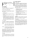
If possible the Installation of a 12 Volt operated refrigerator
should be completed
with
a relay mounted either in the car or in
the recreational vehicle (see
Fig
below
).
This relay
will
auto-
matically
cut out the refrigerator when the car motor IS stopped
r
7