


Before Starting
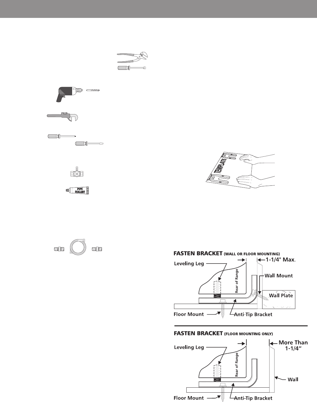
Tools You Will Need
For leveling legs and Anti-Tip Bracket:
• Adjustable wrench or channel lock pliers
• 5/16" Nutdriver or Flat Head Screw Driver
• Electric Drill & 1/8" Diameter Drill Bit (5/32" Masonry Drill
Bit if installing in concrete)
For gas supply connection:
• Pipe wrench
For burner flame adjustment:
• Phillips head and
blade-type screwdrivers
Additional Materials You Will Need
• Gas line shut-off valve
• Pipe joint sealant
• A new flexible metal appliance conduit (1/2" NPT x 3/4"
or 1/2" I.D.) must be design certified by CSA International.
Because solid pipe restricts moving the range we
recommend using a new flexible conduit (4 to 5 foot
length) for each new installation and additional
reinstallations.
• Always use the (2) new flare union adapters (1/2" NPT x
3/4" or 1/2" I.D.) supplied with the new flexible appliance
conduit for connection of the range.
Normal Installation Steps
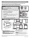
1. Anti-Tip Bracket Installation Instructions
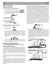
Important Safety Warning
To reduce the risk of tipping of the appliance, the range must
be secured to the floor by properly installed anti-tip bracket and
screws packed with the range. Failure to install the anti-tip
bracket will allow the range to tip over if excessive weight is
placed on an open door or if a child climbs upon it. Serious
injury might result from spilled hot liquids or from the appliance
itself.
If the appliance is ever moved to a different location, the anti-
tip brackets must also be moved and installed with the
appliance.
Instructions are provided for installation in wood or cement
fastened to either the floor or wall. When installed to the wall,
make sure that screws completely penetrate dry wall and are
secured in wood or metal. When fastening to the floor or wall,
be sure that screws do not penetrate electrical wiring or
plumbing.
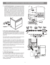
A. Locate the Bracket Using the Template - (Bracket may
be located on either the left or right side of the appliance. Use
the information below to locate the bracket if template is not
available). Mark the floor or wall where left or right side of the
range will be located. If rear of appliance is against the wall or
no further than 1-1/4" from wall when installed, you may use
the wall or floor mount method. If molding is installed and does
not allow the bracket to fit flush against the wall, remove
molding or mount bracket to the floor. For wall mount, locate
the bracket by placing the back edge of the template against
the rear wall and the side edge of template on the mark made
referencing the side of the appliance. Place bracket on top of
template and mark location of the screw holes in wall. If rear
of appliance is further than 1-1/4" from the wall when installed,
attach bracket to the floor. For floor mount, locate the bracket
by placing back edge of the template where the rear of the
range will be located. Mark the location of the screw holes,
shown in template.
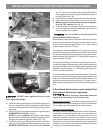
B. Drill Pilot Holes and Fasten Bracket - Drill a 1/8" pilot
hole where screws are to be located. If bracket is to be
mounted to the wall, drill pilot hole at an approximate 20°
downward angle. If bracket is to be mounted to masonry
or ceramic floors, drill a 3/16" pilot hole 1-3/4" deep. The
screws provided may be used in wood or concrete material.
Use a 5/16" nut-driver or flat head screwdriver to secure the
bracket in place.
INSTALLATION INSTRUCTIONS FOR FREESTANDING GAS RANGE
3